Shop project 02 · Revision C

Miter saw + radial arm saw station

A complete, measured build sequence for two mobile 96-inch modules. The RAS faces the operator aisle with its table flush to the worktops; the tall connector cabinet closes behind a door and holds a removable vertical blade pullout.
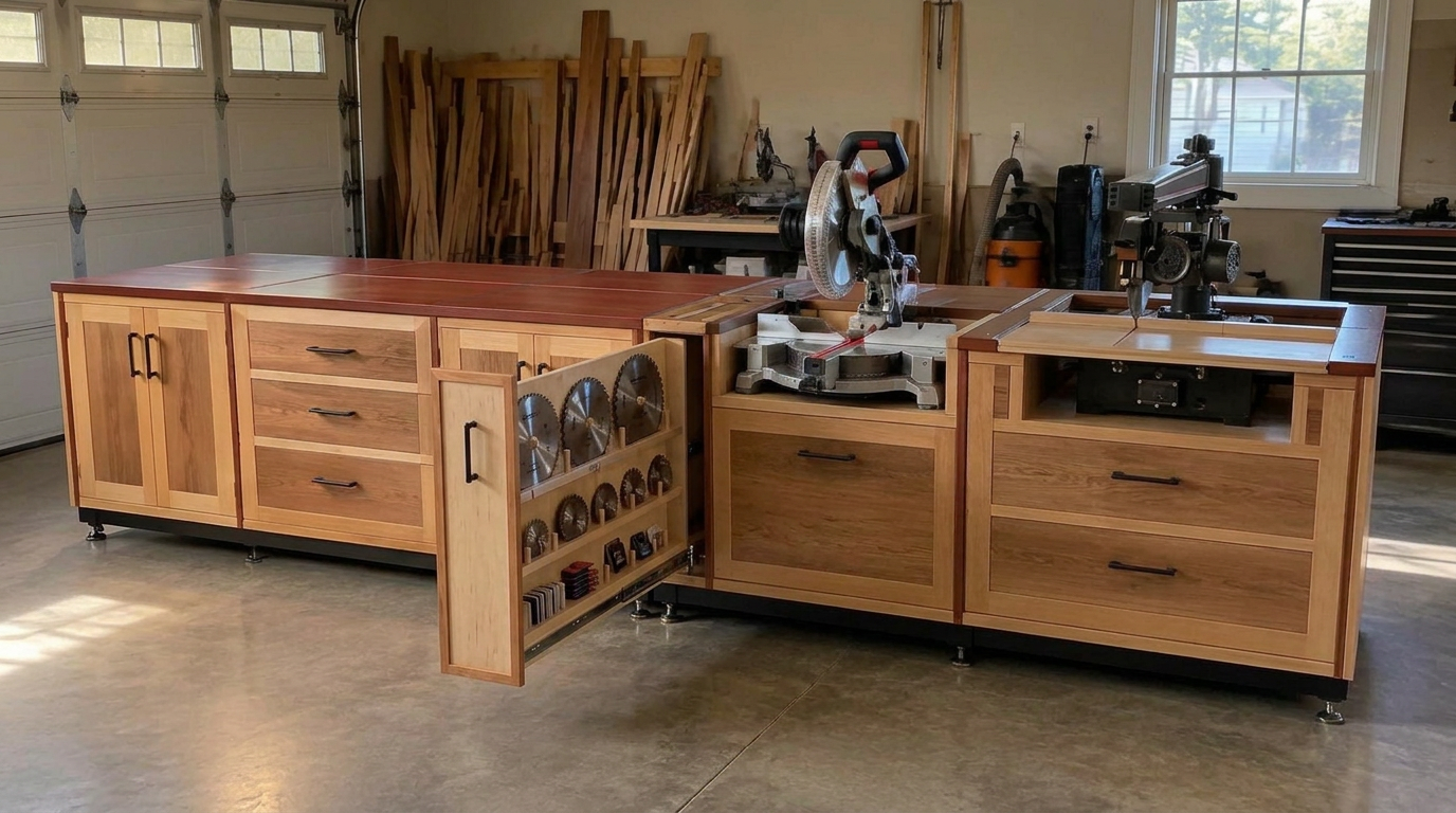
Realistic view of the mobile miter saw and radial arm saw station with the blade-storage pullout open
Design view · blade pullout shown open for inspection
Overall
192 × 30 × 36 in.
Modules
2 × 96 in.
Left module
30 / 36 / 30 in.
Right module
12 / 36 / 48 in.
Carcass depth
24 in. nominal
Finished plane
36 in.

Readiness gate

The design is not released for final cutting.

2 of 13 questions resolved. Prototype and field-fit answers control the dependent cuts; a checked box without a written answer does not count.

2/13decisions closed

Architecture

The full station at a glance

The 96-inch seam falls between the left storage module and the 12-inch connector cabinet. That narrow cabinet stays with the right module and carries the locating and clamping hardware.

30 storage
36 storage
30 storage
12 door + blades
36 Bosch
48 front-facing RAS
Left module · 96 in.Right module · 96 in.

Phase 1 · Prototype

One caster station, built full size

A single FOOT MASTER GDH-75-ASF-NYD-FBL bolted through a full-thickness LSL pad, with a scrap plywood panel standing in for the cabinet bottom. It proves the pad thickness, bolt pattern, access-hole diameter, swivel clearance, and the real support-plane height before any plinth material is cut.

The pad is laminated to 3 in. total thickness so the through-bolts and 1-1/4 in. access hole have enough material to stay true under load. Two layers of 2×4 or 2×6 LSL scraps are enough; cross the strand directions when gluing so the pad resists splitting and creep.
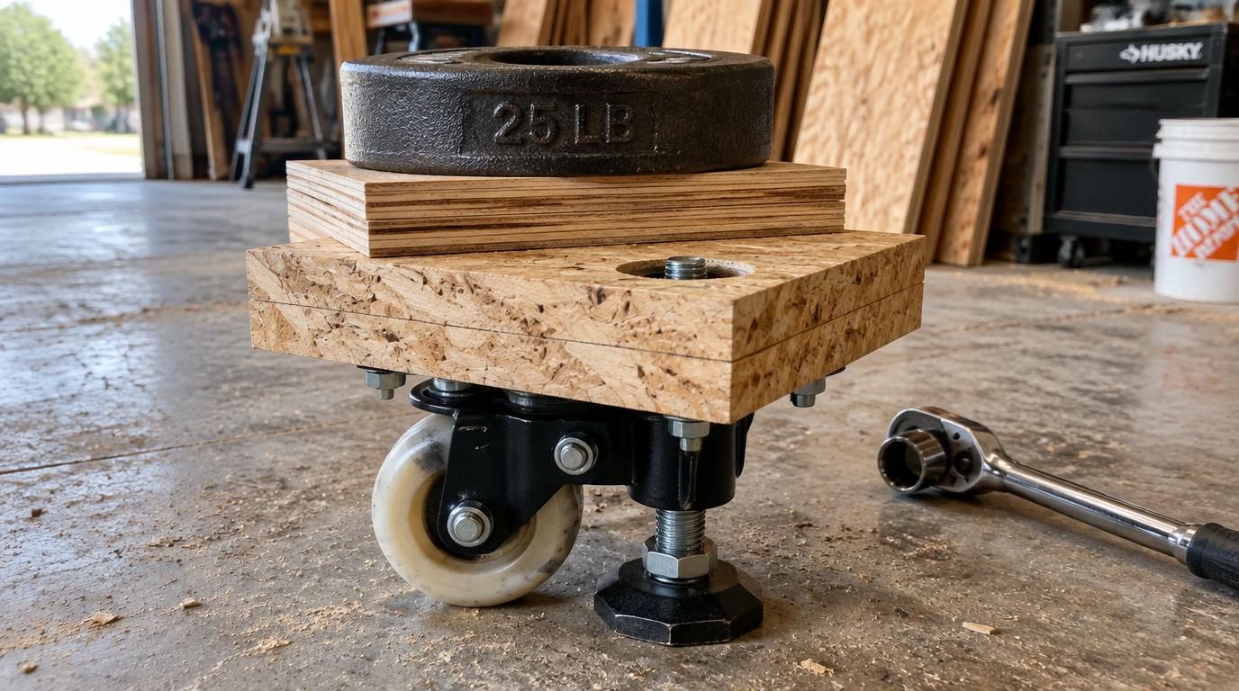
Prototype caster mounting pad: laminated strand lumber pad with a black leveling caster bolted underneath, leveling foot deployed on a garage floor and a loaded stack on top
Prototype view · foot deployed, wheel unloaded, socket access open

Parts and dimensions

Pad, two LSL layers6 × 6 in. × 2 × 1-1/2 in. (3 in. total)
2×4 or 2×6 LSL scraps work fine. Glue and screw the laminations; cross strand directions between layers if possible.
Caster plate footprint90 × 90 mm (3-1/2 in.)
Centered on the pad; leaves ~1-1/4 in. of pad outside the plate on all sides.
Through-bolt pattern70 × 70 mm square, 9.5 mm holes
M8 or 3/8 in. hex bolts, 4-1/2 in. long, flat washer + lock washer + nut on top.
Leveling-shaft access hole1-1/4 in. dia., pad center
Drill from the top with a Forstner bit; enlarge only if the socket binds.
Simulated cabinet bottom12 × 12 in. of 3/4 in. plywood
Screwed to the pad so the socket reach matches the real cabinet interior.
Test load300–500 lb of sheet goods or weights
Stack over the pad center; leave loaded for 24 hours before re-measuring.
Measurement to recordTarget / acceptance
Rolling height (feet retracted)≈110 mm / 4-5/16 in. plate bottom to floor
Deployed height (foot down, wheel free)Up to 145 mm / 5-11/16 in. — record the actual working setting
Wheel unloadWheel spins freely by hand with the pad fully loaded
Swivel sweep clearance64 mm offset — no contact through a full 360° rotation
Socket accessStraight, un-cocked engagement on the M16 nut through the hole
Pad integrity after 24 h loadNo crushing under washers, no pull-through, no splitting, no creep

Controlled dimensions

Know what is fixed—and what is not

ItemValueRelease status
Finished worktop192 × 30 × 36 in.Controlled
Each movable module96 in. longControlled
Top stack3/4 in. plywood + 1/2 in. MDF + laminateControlled
Top of carcass34-3/4 in. targetMeasure
Bosch platformJack-screw adjusters, height field-fit from inside the cabinetField-fit
RAS tableFlush at 36 in.; saw faces frontField-fit
LSL plinth crossmembers21 in.Controlled
Caster pads and access holesSize from actual hardwarePrototype

Before completing the design

Questions to answer before cutting

Record the measured or selected value, then mark it resolved. Each card names the work that must wait.

Saved on this device

Q01Prototype

What is the final caster model and capacity?

Confirm plate geometry, foot travel, and capacity at the most heavily loaded caster line.

Blocks: Plinth batch cutting
Q02Prototype

What are the mounting-plate and through-bolt dimensions?

They determine pad size, edge distance, blocking, and fastener length.

Blocks: Caster pads
Q03Measure

What is the loaded plinth support-plane height?

Carcass height must be calculated from the real prototype, not a catalog drawing.

Blocks: Carcass side panels
Q04Prototype

Which socket and access-hole diameter provide straight adjustment?

All twelve leveling feet must remain accessible from inside the cabinets.

Blocks: Access holes
Q05Measure

What is each module’s estimated fully loaded weight?

Caster selection and safe relocation depend on realistic machine, cabinet, top, and storage loads.

Blocks: Caster approval
Q06Field-fit

What are the blade pullout’s clear inside dimensions?

The door, slides, pegs, tooth spacing, dado storage, and connector access must coexist in 12 inches.

Blocks: Door and blade pullout
Q07Field-fit

What is the Bosch platform footprint and full movement envelope?

The shelf and adjusters cannot interfere with bevel, glide, battery, controls, or dust hose.

Blocks: Bosch bay
Q08Field-fit

What deck height and clearances does the front-facing RAS require?

Measure crank sweep, column, carriage, blade, guard, fence, and rear hose on the actual saw.

Blocks: RAS bay
Q09Measure

Is the RAS guard and recall status confirmed?

Do not energize the saw until the official remedy and full blade guard requirements are satisfied.

Blocks: RAS operation
Q10Design

Which laminate goes on each module?

Assign the available sheets before cutting and bonding the top skins.

Blocks: Worktops
Q11Design

How will dust collection and electrical service be routed?

Hoses and cords need service loops without crossing controls, pullouts, or blade travel.

Blocks: Storage fronts
Q12Field-fit

Where do the three 48-inch Combo Tracks land after calibration?

Track recesses are routed only after both machines and the full 16-foot plane are stable.

Blocks: Track routing
Q13Measure

Can each 96-inch module pass through the relocation route safely?

Verify doorway width, turns, handling weight, and which tops or boxes must detach.

Blocks: Final assembly strategy

Construction sequence

Twelve phases, in dependency order

0/57 build tasks
  1. 010/5

    Prototype one caster station

    Prerequisite

    Actual caster, socket, bolts, and representative LSL/cabinet material in hand.

    • Confirm the delivered FOOT MASTER GDH-75-ASF-NYD-FBL caster matches HVH order 26-16066C.
    • Laminate a full-size mounting pad and through-bolt the caster.
    • Verify 360° swivel, wheel clearance, foot travel, and straight socket access.
    • Load the sample; inspect for crushing, pull-through, splitting, sliding, and creep.
    • Record the loaded support-plane height.

    Stop condition

    Do not duplicate pads or drill all twelve access holes until the prototype passes.

    Acceptance

    Wheel unloads completely; foot is stable; adjustment remains accessible.

    Single leveling caster through-bolted to a laminated LSL pad as a prototype station
    Prototype caster station · one laminated pad, one caster, socket access proven before repeating it twelve times
  2. 020/5

    Build both LSL plinths

    Prerequisite

    Phase 1 dimensions recorded and caster capacity approved.

    Materials for this trip

    2×6 LSL2 × 20 ft
    2×4 or 2×6 LSL15 × 21 in.

    Four 96 in. rails; leaves ~8 ft margin for miscuts. Crossmembers. Use existing 2×4 scraps to avoid buying a third 20 ft 2×6.

    • Cut four 96-inch long rails from 2×6 LSL on edge. 2×4 LSL is acceptable only if laminated face-to-face into a 3 × 3-1/2 in. beam, or capped with a flat 2×4 to form an L-girder.
    • Cut fifteen 21-inch crossmembers from 2×4 or 2×6 LSL.
    • Build the left plinth rails at 0, 6, 30, 48, 66, 90, and 96 inches.
    • Build the right plinth rails at 0, 6, 12, 42, 48, 72, 90, and 96 inches.
    • Install twelve laminated 3-inch pads and casters at the tested support lines.

    Stop condition

    Reject any twisted assembly or fastener with inadequate edge distance.

    Acceptance

    Both plinths are square, flat, rigid, and roll freely with feet retracted.
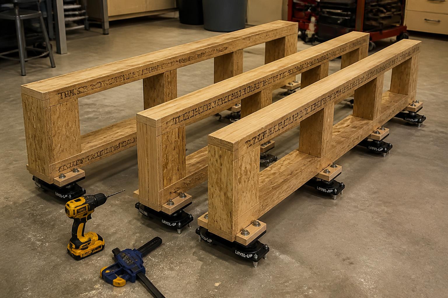
    Two 96-inch LSL plinth frames on edge with twelve leveling casters bolted to laminated pads
    Plinth build · four 96-inch rails, fifteen crossmembers, twelve casters on laminated pads
  3. 030/4

    Establish carcass height

    Prerequisite

    Both loaded plinths can be positioned on the actual garage floor.

    • Level each plinth on deployed feet without forcing twist.
    • Measure floor-to-carcass support plane at multiple points.
    • Include actual plywood, MDF, laminate, and adhesive thicknesses.
    • Calculate cabinet side height to place the finished plane at 36 inches.

    Stop condition

    Do not batch-cut cabinet sides from nominal caster dimensions.

    Acceptance

    A written side-panel height produces the 34-3/4-inch carcass target.
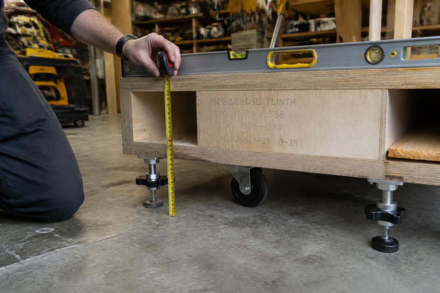
    Measuring floor-to-support-plane height on a plinth standing on deployed leveling feet
    Height take-off · measure the loaded support plane, then back-calculate the cabinet side height
  4. 040/4

    Build the cabinet carcasses

    Prerequisite

    Carcass height and service-hole positions are released.

    • Build three independent left boxes: 30, 36, and 30 inches wide.
    • Build the full-height 12-inch connector cabinet, 36-inch Bosch bay, and 48-inch RAS bay.
    • Use 3/4-inch prefinished birch; add backs, gussets, or deep stretchers where required.
    • Anchor loads into LSL or blocking—not plywood edges—and preserve caster access.

    Stop condition

    Do not let partitions cover top-adjustment holes or connector hardware.

    Acceptance

    Boxes are square, independently rigid, and fit their marked plinth positions.
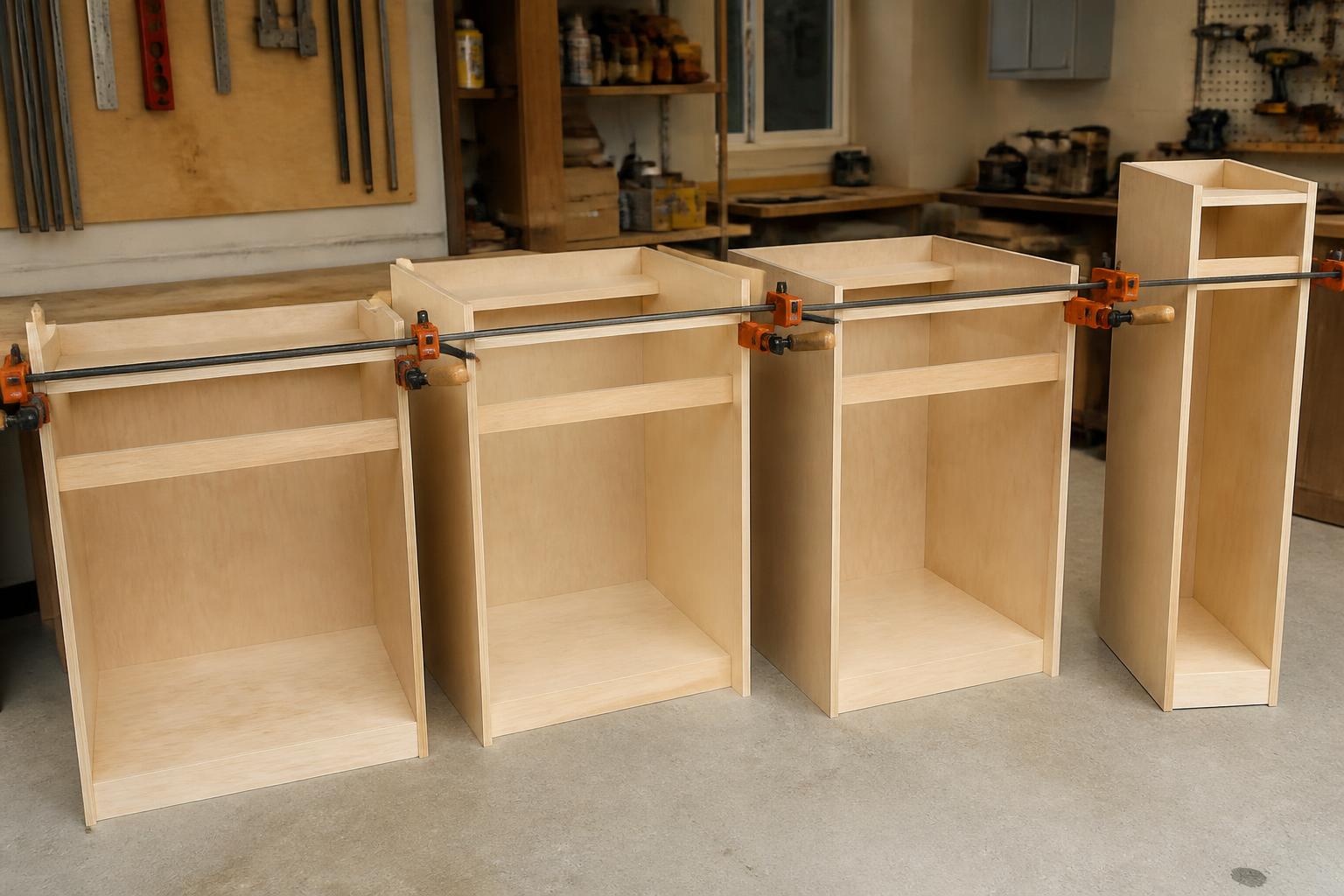
    Prefinished birch plywood cabinet carcasses of several widths clamped square in the shop
    Carcass build · independent boxes, square and rigid, each sized to its marked plinth position
  5. 050/8

    Install the module connection

    Prerequisite

    Both 96-inch modules are level, their joining faces are square, and the 12-inch connector cabinet is open.

    • Build the connection inside the 12-inch connector cabinet so it is hidden behind the closed door.
    • Reinforce the joining faces with solid blocking where they meet inside the cabinet.
    • Install T-nuts flush into the left module's joining face, oriented for the right module's knobs.
    • Install one upper and one lower locating pin between the module faces.
    • Drill matching clearance holes through the right module's joining face for the threaded knobs.
    • Thread the knobs from inside the right module cabinet into the T-nuts on the left module; keep knob heads clear of the blade pullout.
    • Check that the vertical blade pullout can slide past or be removed without touching the fasteners.
    • Separate and reconnect repeatedly while checking alignment.

    Stop condition

    Do not let T-nuts, knob heads, or pins project into the blade pullout's travel or storage volume.

    Acceptance

    The seam closes repeatably without forcing, racking, or loss of elevation, and all fasteners stay hidden behind the closed door.
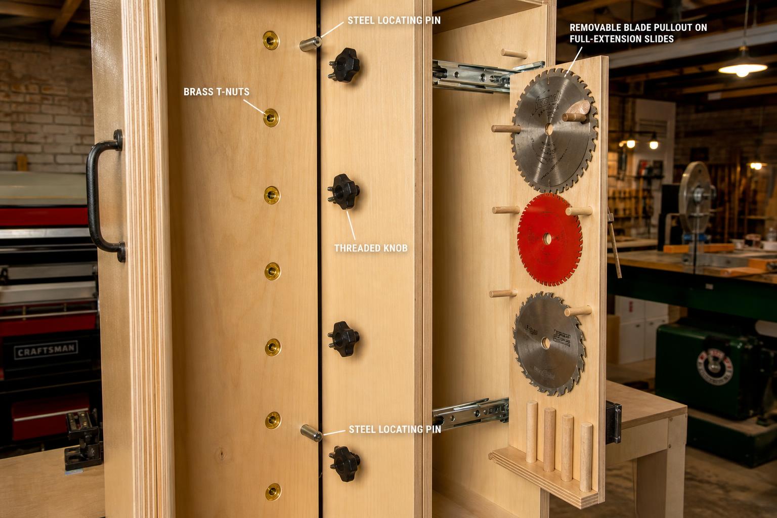
    Interior of the 12-inch connector cabinet with T-nuts in the left module face, threaded knobs from the right module, and the blade pullout slid aside
    Module connection detail · T-nuts in the left module face accept threaded knobs from inside the right module cabinet, hidden behind the closed door
  6. 060/4

    Fit the door and blade pullout

    Prerequisite

    Connector fasteners and caster access locations are fixed.

    • Hang a full-height door on the 12-inch connector cabinet.
    • Build a removable vertical plywood pullout on full-extension slides.
    • Space pegs so carbide teeth never touch; add compact dado chip, shim, and flange storage.
    • Test door swing, pullout travel, latch, module bolts, and caster adjustment access.

    Stop condition

    The pullout must not carry structural joining load or open into either machine.

    Acceptance

    Door closes securely; pullout removes for service and protects every blade.
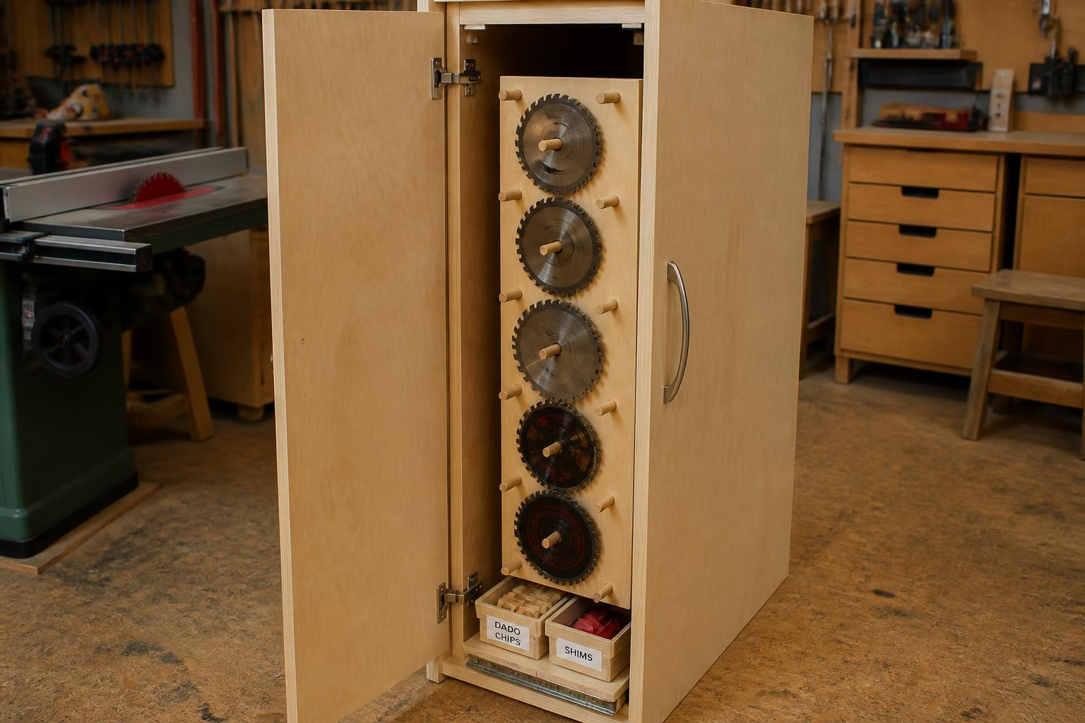
    Tall narrow cabinet with its door open showing a vertical blade pullout on full-extension slides
    Door and blade pullout · spaced pegs keep carbide teeth clear, and the pullout lifts out for service
  7. 070/6

    Build the Bosch platform

    Prerequisite

    Actual saw footprint and full glide/bevel envelope are measured.

    • Install a fixed lower shelf or solid block inside the Bosch bay to act as the support plane.
    • Cut a separate 3/4-inch plywood platform sized to the saw base plus clearance.
    • Drill the platform corners for 3/8-inch-16 jack screws with steel bearing plates underneath; add separate 5/16-inch-18 hold-down bolts with washers to clamp the platform without relying on the jack screws.
    • Fit UHMW anti-sway guides against the cabinet sides so the platform cannot shift laterally under thrust or vibration.
    • Rough-set the platform near 32-1/4 inches, then fine-adjust each corner from inside the cabinet below — this avoids reaching between the cabinet top and the platform.
    • Mount the saw with manufacturer-approved hardware and verify every control position.

    Stop condition

    Do not close the bay until battery, bevel, glide, guard, and hose access are proven, and the platform cannot shift under thrust or vibration.

    Acceptance

    Saw table adjusts flush in both axes from inside the cabinet below, locks without movement, and the jack-screw + hold-down + anti-sway hardware keeps the platform square and laterally supported.
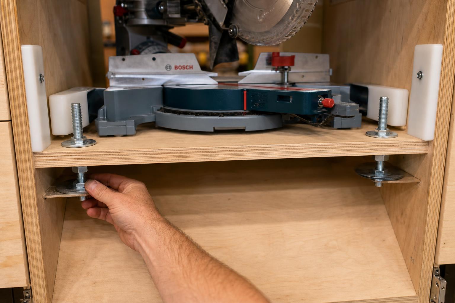
    Bosch miter saw platform with jack screws, steel bearing plates, hold-down bolts, and UHMW anti-sway guides adjusted from inside the cabinet below
    Bosch platform detail · jack screws and hold-downs adjusted from inside the cabinet, where there is full forearm clearance
  8. 080/5

    Field-fit the radial arm saw

    Prerequisite

    Guard/recall status resolved and actual machine geometry recorded.

    • Orient the saw toward the cabinet front and operator aisle.
    • Build a reinforced support deck tied into cabinet sides and the plinth.
    • Provide the replaceable table and fence geometry required by the manufacturer.
    • Shim or adjust until the RAS table is exactly flush with both adjacent surfaces.
    • Sweep crank, carriage, blade, column, guard, and hose through full travel.

    Stop condition

    Do not energize the saw with unresolved guard status or any collision.

    Acceptance

    Front-facing saw is secure, guarded, operable, and flush at 36 inches.
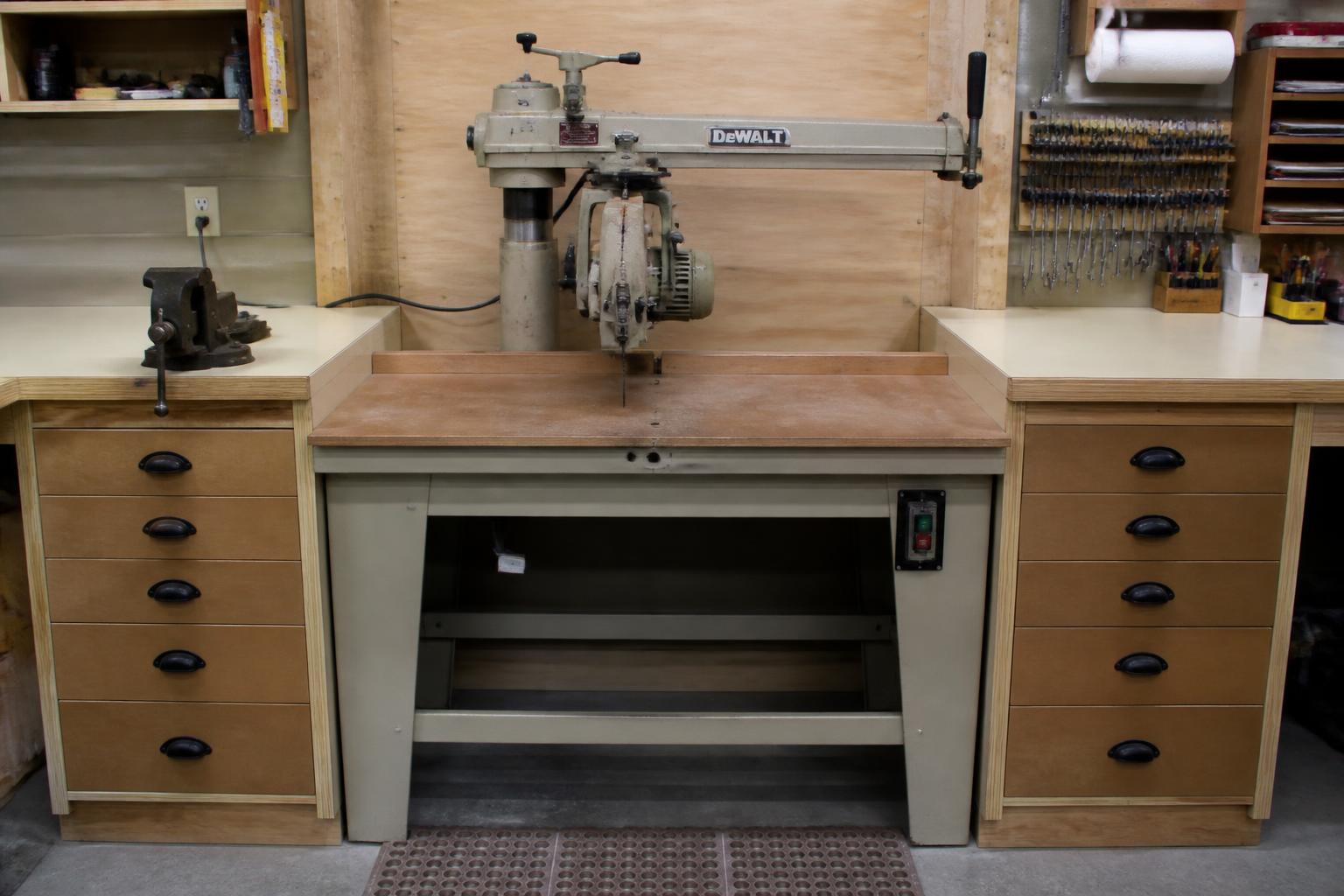
    Radial arm saw mounted front-facing in its cabinet bay with the table flush to the worktops on both sides
    Radial arm saw field-fit · saw faces the front, table shimmed exactly flush at 36 inches
  9. 090/4

    Build and laminate worktops

    Prerequisite

    Both machine elevations and all required cutouts are field-verified.

    • Build the 3/4-inch plywood and 1/2-inch MDF structural stack.
    • Apply assigned Wilsonart laminate and finish cherry edging near 1-1/4 inches.
    • Field-fit right-side surfaces around the connector, Bosch, and RAS areas.
    • Keep tops removable where needed for relocation and service.

    Stop condition

    Do not assume the right module is one uninterrupted rectangular top.

    Acceptance

    Surfaces are flat, stable, cleanly edged, and ready for calibration.
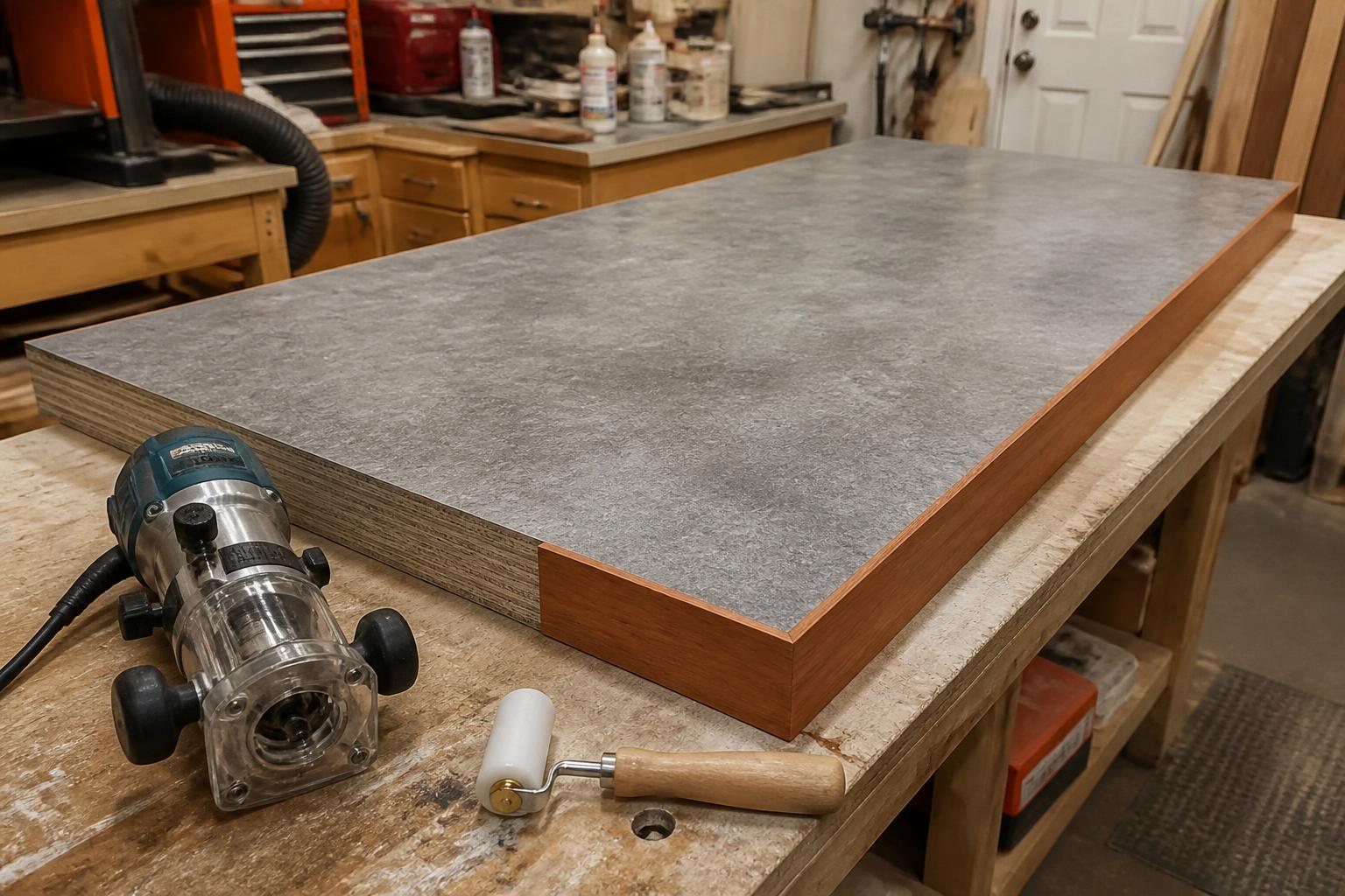
    Laminated worktop with a plywood and MDF core, grey laminate face, and solid cherry edging
    Worktops · plywood and MDF core, Wilsonart laminate face, cherry edge near 1-1/4 inches
  10. 100/4

    Connect, level, and calibrate

    Prerequisite

    Both complete modules are in their final operating position.

    • Retract feet, position modules, engage pins, and install bolts finger-tight.
    • Lower three widely spaced feet per module to establish planes; bring the rest into shared contact.
    • Unload all wheels, equalize module elevations, tighten bolts, and recheck the seam.
    • Adjust Bosch and front-facing RAS surfaces flush to the full 192-inch plane.

    Stop condition

    Never force one foot far enough to twist a plinth or open the seam.

    Acceptance

    Long straightedge and laser show one stable plane with no rocking.
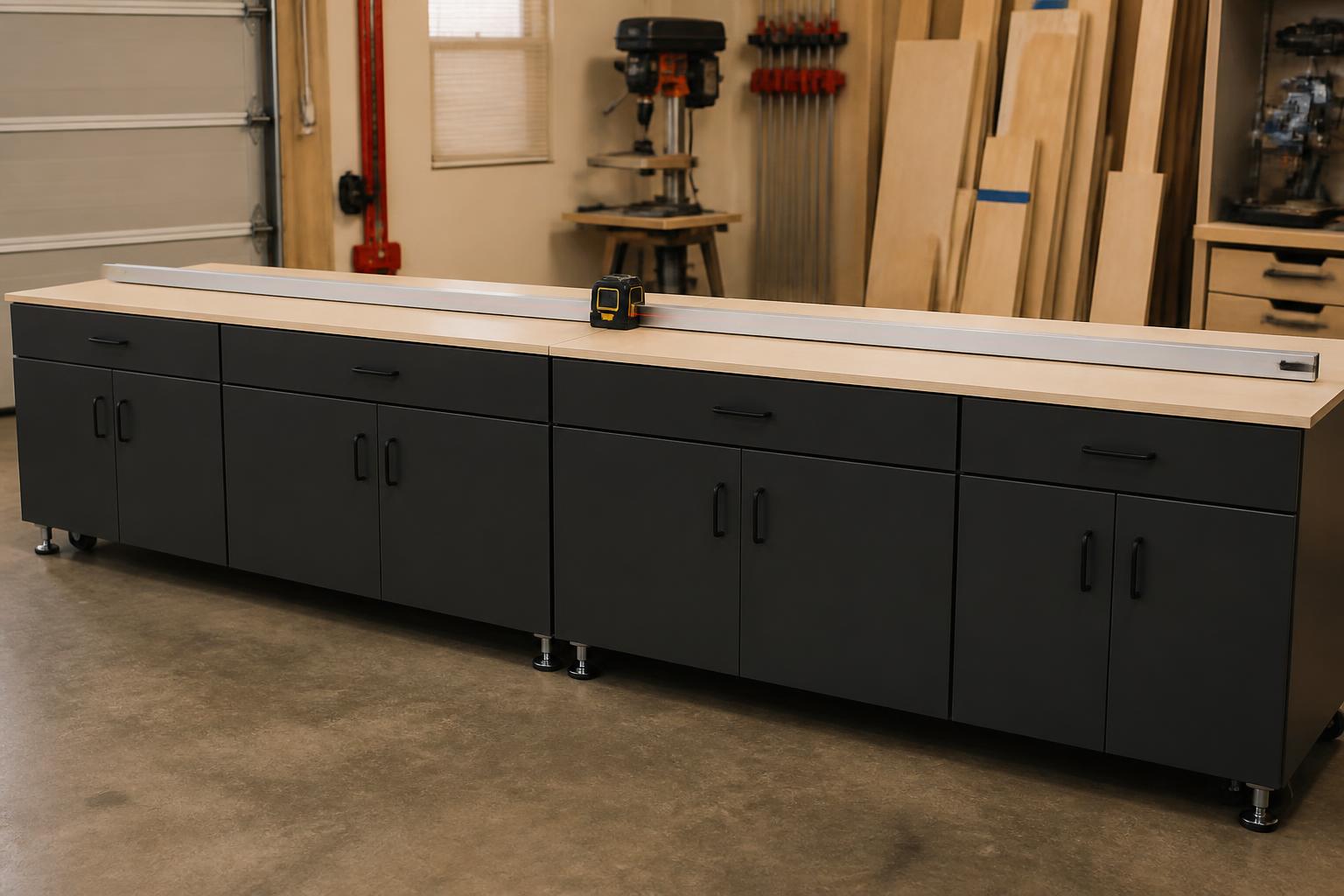
    Two joined cabinet modules checked with a long straightedge and laser across the seam
    Connect and level · straightedge and laser confirm one stable plane with every wheel unloaded
  11. 110/4

    Route and install Combo Tracks

    Prerequisite

    The complete plane remains stable through alignment and test cuts.

    • Mark the final centerlines across the calibrated surfaces.
    • Confirm stops cannot enter either blade path.
    • Route shallow recesses for three 48-inch tracks.
    • Install tracks flush and verify stop travel across working zones.

    Stop condition

    Do not route early; machine or seam adjustments would invalidate the recesses.

    Acceptance

    Tracks are flush, aligned, secure, and clear of every blade.
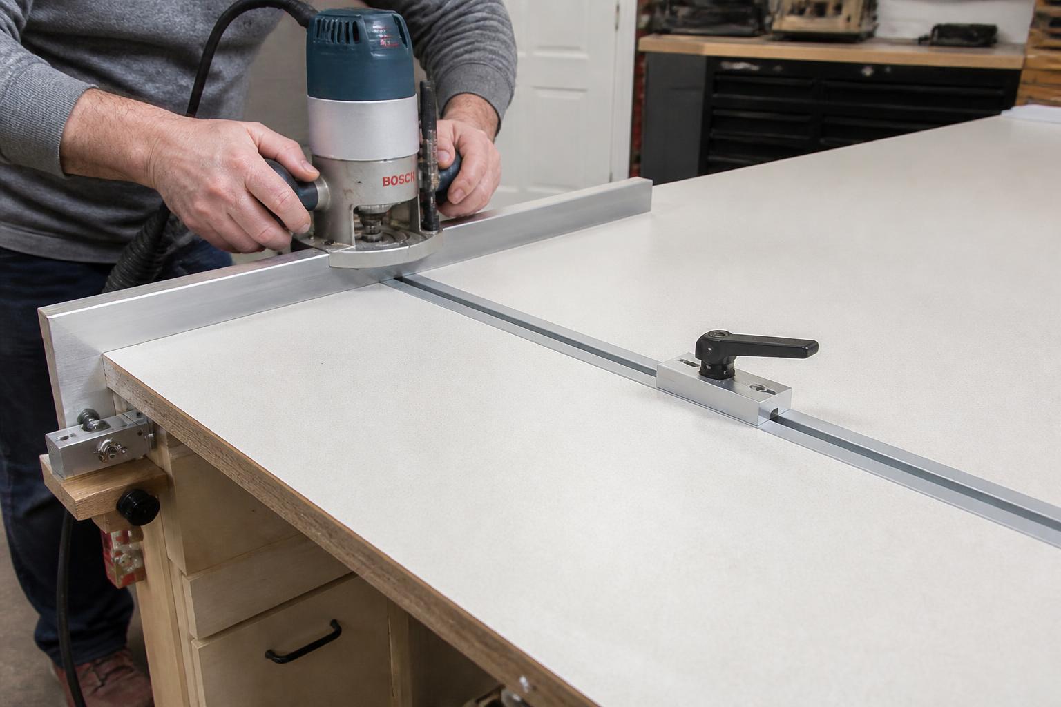
    Routing a shallow recess in a worktop for an aluminum measuring track with a flip stop
    Combo Tracks · shallow recesses cut last, tracks flush, stops clear of every blade path
  12. 120/4

    Complete storage and commission

    Prerequisite

    Structure, machines, tracks, dust, and electrical paths are final.

    • Fit remaining drawers, doors, shelves, pulls, removable panels, and dust details.
    • Confirm no storage front blocks a foot, bolt, control, cord, or hose.
    • Perform the full safety and definition-of-done checklists.
    • Record baseline dimensions and photographs for future reassembly.

    Stop condition

    Cosmetic completion does not override a failed mechanical or safety check.

    Acceptance

    Station is rigid, mobile, serviceable, safe, and repeatably aligned.
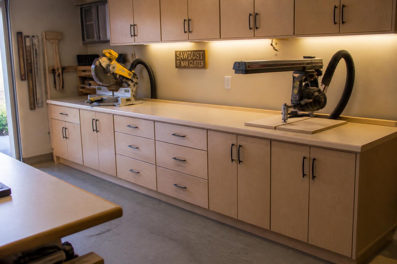
    Finished 16-foot miter saw and radial arm saw station with drawers, doors, and dust hoses in place
    Commissioning · storage fitted, dust routed, nothing blocking a foot, bolt, control, or hose

Safety gate

Safety before use

  • RAS model, serial, recall remedy, and full blade guard are confirmed.
  • All guards, anti-kickback devices, fences, and tables follow manufacturer instructions.
  • All twelve wheels are visibly unloaded before either saw runs.
  • Caster plates, pads, bolts, and LSL show no crushing, splitting, or pull-through.
  • Modules are rigid, level, connected, and closed at the seam.
  • Bosch and RAS tables are flush with adjacent surfaces.
  • RAS faces front; crank, carriage, column, blade, guard, and hose move freely.
  • Blade pullout latches behind its door and cannot enter a machine path.
  • Electrical supply, breaker capacity, cords, and dust hoses are safe and serviceable.
  • Combo Tracks are flush and stops cannot contact a blade.
  • Long-stock support and the operator aisle are clear.
  • Fasteners and calibration are rechecked after relocation or impact.

Commissioning

Definition of done

  • Both modules are square, rigid, and free of twist.
  • Each module rolls cleanly with all leveling pads retracted.
  • All pads adjust from above and unload every wheel when deployed.
  • Pins and bolts repeatedly return the seam to alignment.
  • Bosch and front-facing RAS surfaces are flush with adjacent tops.
  • The full 192-inch plane passes straightedge and laser checks.
  • No control, blade path, crank, carriage, cord, hose, door, or pullout is obstructed.
  • Modules separate without damage and fit the verified relocation route.
  • All guard, recall, and manufacturer requirements are satisfied.
  • Baseline measurements and photographs are saved.

Overall record

0 of 79 checks complete · 2 of 13 decisions closed

Download packet