Shop project 03 · Build sequence
Cradle build guide
From nested triangle layers on the temporary LowRider deck to a rolling, stabilizer-locked cradle and its removable datum rail — three phases, eleven steps, with hold points wherever engineering must land first.
Tooling
Router bits for the build
Every cut in this guide runs on one of these bits — the first three are the only ones worth buying specifically for the cradle. Prices are estimates; confirm at the linked supplier before ordering.
- 01
1/4 in. compression spiral (up-down)
≈ $32
Through-cutting every 3/4 in. triangle layer and pad — clean veneer on both faces in one pass. The DXF README cut parameters assume this bit.
The one bit worth buying specifically for this build if you don't already own a compression bit.
- 02
1/4 in. downcut spiral
≈ $18
Backup profile cutter and the safer choice for the small pads — down-shear holds the work down and leaves a crisp top face.
Slower chip evacuation, so take shallower passes than the compression bit.
- 03
1/2 in. flush-trim (template) bit
≈ $40
Flushing the laminated 2-1/4 in. end-frame edges to each other after glue-up, if the stacked layers don't go back on the CNC for profiling.
Run in a handheld router against a template or the CNC-milled master layer.
- 04
1 in. Forstner bit
≈ $12
Placeholder pivot bore — final diameter waits on the measured mass and the chosen bearings.
Do not drill the pivot bore until the hold is released — any sharp 1 in. Forstner works when the time comes.
- 05
3/8 in. brad-point or jobber drill
≈ $8
Through-bolt clearance holes for the caster pads, bearing pads, and leveler blocks.
Drill press preferred; the holes must run square through the lamination stack.
- 06
1/8 in. round-over bit (optional)
≈ $15
Edge-breaking only — the striped laminated edges are the finish, so hand-sanding the corners works just as well.
Skip it if you already ease edges by hand.
Bits sourced from Bits & Bits (bitsbits.com) — a LowRider-community staple — with the ordinary drill bits linked to Rockler’s search since individual sizes rotate in stock. The spoilboard surfacing bit you already own covers the temporary table.
Phase one
Mill the parts on the temporary CNC table
- 01
Confirm the temporary table is accurate
Every cradle part is cut on the temporary LowRider deck, so its accuracy becomes the cradle's accuracy.
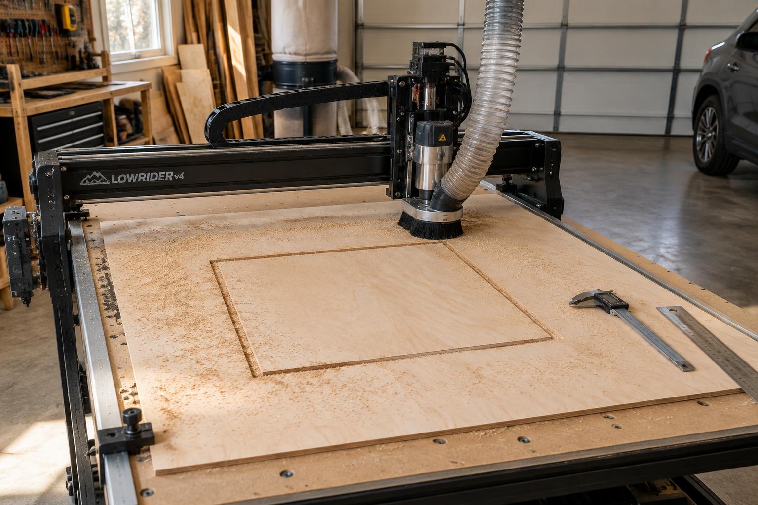
Concept reference — not a fabrication drawing - Surface or skim the temporary spoilboard so it is flat.
- Verify the machine cuts square: mill a five-cut test square and measure both diagonals.
- Measure actual cut dimensions against the program on a test coupon — do not trust the drawing until the machine proves it.
Do not cut cradle parts until the test square and coupon pass.
- 02
Nest the triangle layers
Each end frame is a stack of identical rounded-triangle layers cut from 3/4 in. Baltic birch.
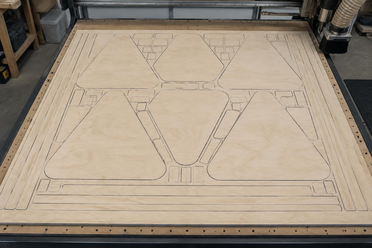
Concept reference — not a fabrication drawing - Pick your sheet size first: the 5 × 5 ft nest uses five sheets and needs a sixth inner triangle layer from an offcut; the 4 × 8 ft nest fits two triangle layers per sheet (one upright, one flipped), so three sheets yield all six layers plus every pad with spares.
- Nest all layers for both end frames plus the caster pads, bearing pads, and leveler blocks — the spine is a 2 × 6 LSL, so no plywood spine strips are nested at all.
- On 4 × 8 sheets, run the 96 in. edge along the table's long axis — the nested pair of triangles needs 87 in. of length and 40 in. of cross travel.
- Leave at least a bit's diameter between parts; add tabs or onion-skin the bottom 1/16 in. so small pads do not shift.
- Include the caster pads, bearing pads, and leveler blocks in the same nest so every lamination comes from the same material batch.
- Export the toolpaths and dry-run one sheet above the table to confirm clearance.
- The ready-made DXF nests above are the starting layouts — download the one matching your sheets, adjust the toolpaths for your bit, and verify it against your own machine before cutting.
- Use the separate datum-rail download for the full-size 49 in. and 97 in. maple profiles, opposing-face half-lap layers, router-bit specifications, and mounting checklist. These are hardwood-stock files, not plywood parts.
- 03
Mill the layers
Cut every layer in one session if possible so edge quality and dimensions stay consistent.
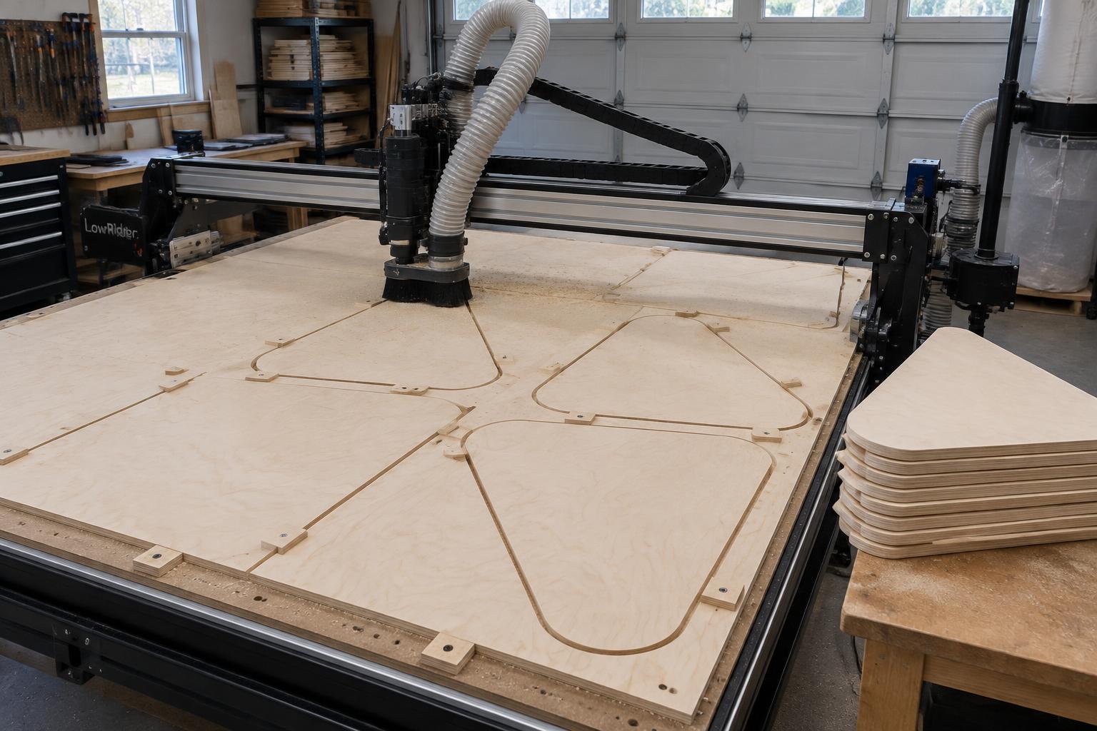
Concept reference — not a fabrication drawing - Use a sharp 1/4 in. compression or downcut bit for clean top and bottom faces on the birch veneer.
- Cut in two or three passes at a conservative feed; Baltic birch dulls bits and burns if pushed.
- Label each layer for frame A or B and its stack position as it comes off the table.
- Check one layer of each part against the program with calipers before cutting the rest.
Pause after the first full set of layers — confirm the triangle base width nests against the 62 in. footprint requirement before cutting the rest.
Phase two
Laminate and finish the frames
- 04
Laminate the end frames
Full glue coverage between layers; the striped plies on the rounded edges are the finished surface.
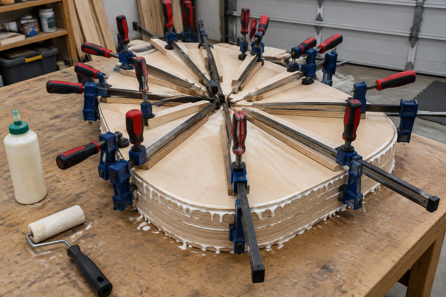
Concept reference — not a fabrication drawing - Dry-stack each frame and clamp it to confirm the layers register; mark alignment edges.
- Spread glue evenly over the full face of every layer — no starved glue lines.
- Clamp from the center outward with cauls so the triangle's edges do not cup.
- Let each frame cure fully before unclamping; do not rush the schedule to free clamps.
- 05
Mill the laminated frames to final shape
After glue-up, return each frame to the temporary table for its finished edges and holes.
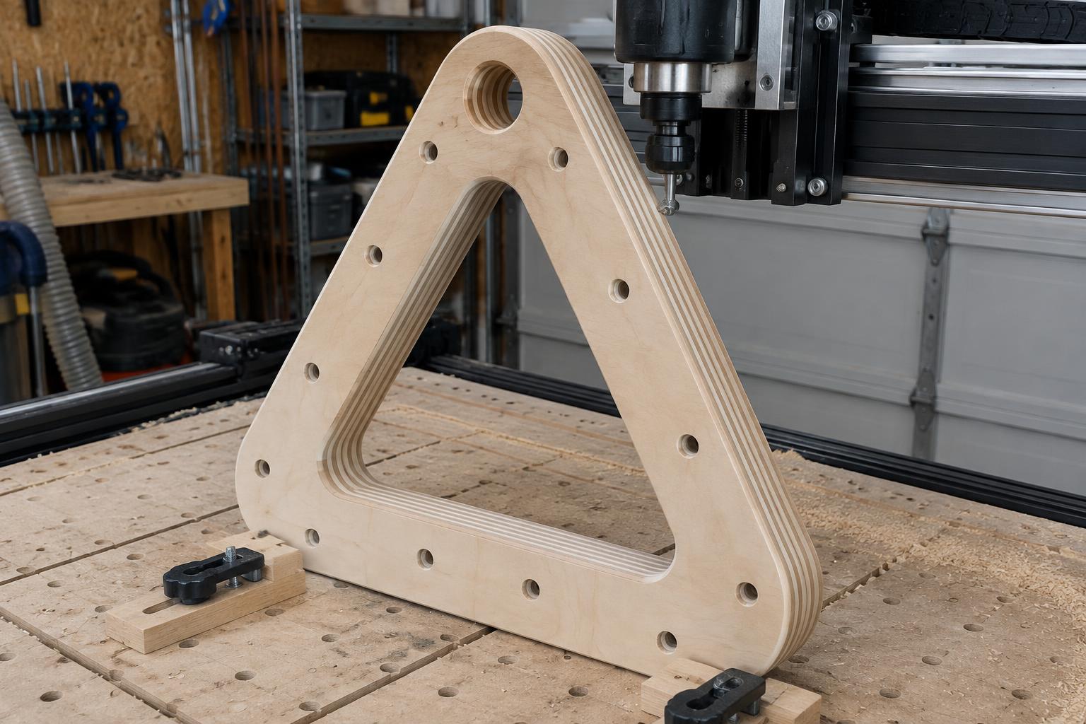
Concept reference — not a fabrication drawing - Mill the rounded edges of the laminated stack so every ply's stripe runs flush and continuous.
- Bore the pivot bearing location and drill the through-bolt pattern for the bearing pads and reinforcement plates — sizes stay placeholder until the pivot engineering lands.
- Drill the caster pad and leveler block mounting patterns.
- Break sharp edges lightly; the lamination stripes are the finish, so no edge banding.
Pivot bore diameter and bolt pattern are on hold — verify against the measured mass and chosen bearings before cutting.
- 06
Cut and fit the LSL spine
A single 2 × 6 LSL joins the end frames at floor level — factory-laminated, so this step has no glue-up at all; no side rails, no middle crossbeam.
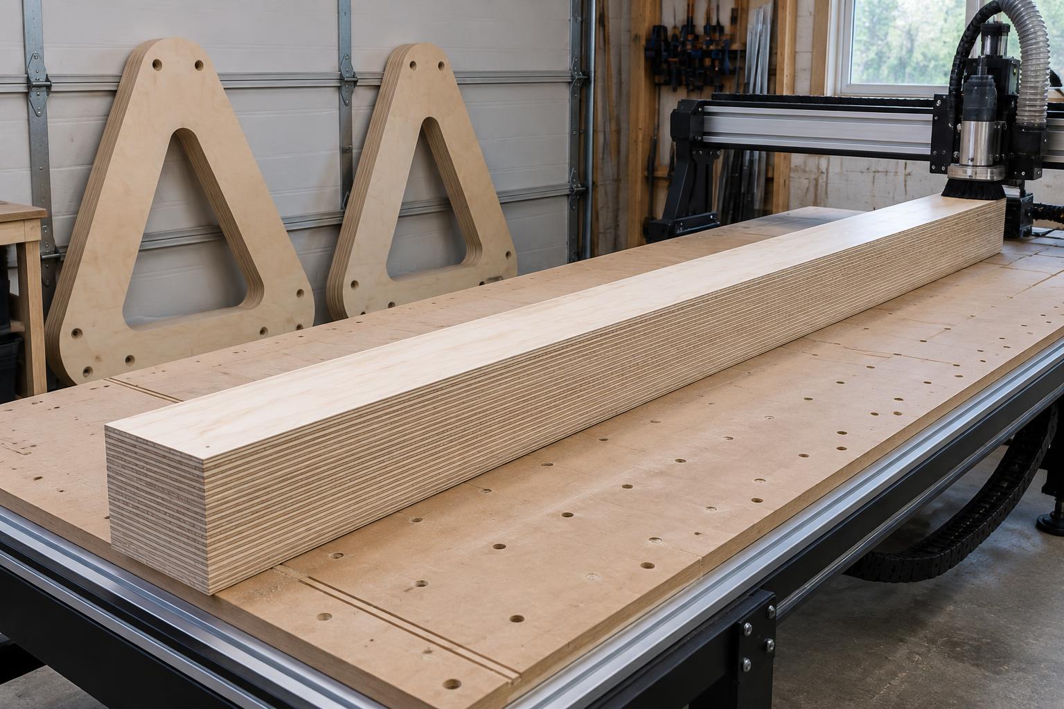
Concept reference — not a fabrication drawing - Cut the LSL to the final ≈ 112–120 in. length and square both ends on the temporary table or with a guided circular saw.
- Scuff-sand the gluing faces at the frame joints; LSL's waxy surface needs 80–120 grit for the adhesive to bite.
- Cut the joints where the spine meets each end frame — a housed or through-bolted joint that resists racking along the 112 in. length.
- The DXF nests contain no spine strips — the LSL is the whole spine, cut square to length and joined at the end frames.
Phase three
Assemble the cradle
- 07
Make and calibrate the datum rail
Two removable hard-maple strips form the front-left X0/Y0 reference after the permanent work surface is fitted.
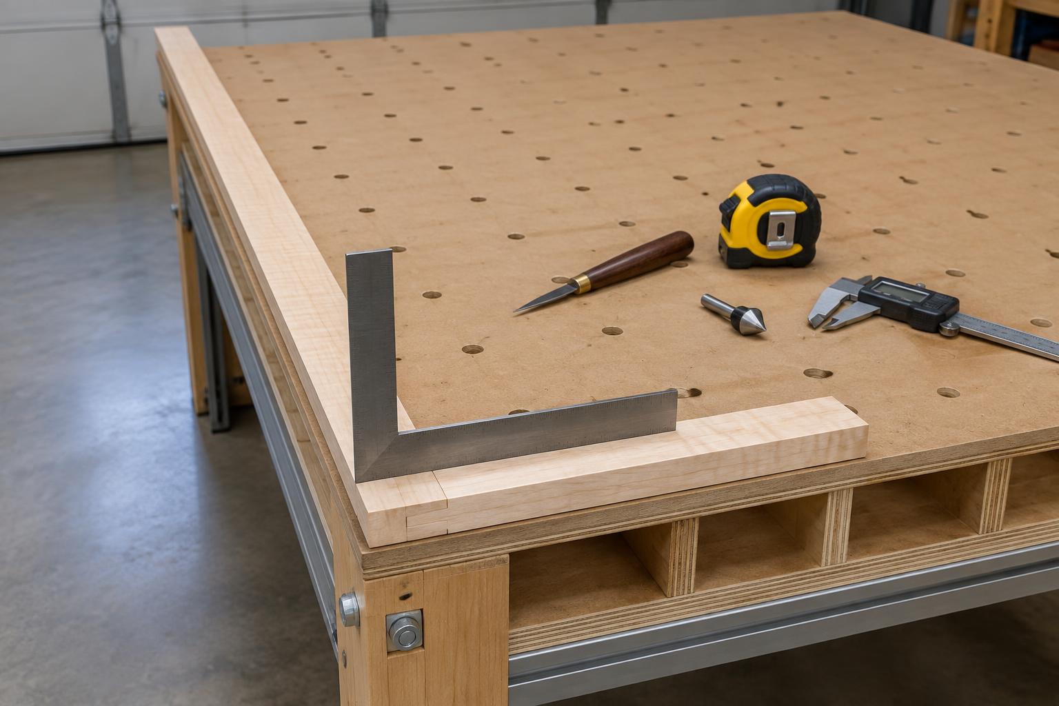
Concept reference — not a fabrication drawing - Mill two straight hard-maple blanks to a finished 3/4 in. thickness and 1-1/2 in. width. Cut the front/Y0 rail to 49 in. and the left/X0 rail to 97 in.
- At the front-left corner, cut a 1-1/2 × 1-1/2 in. half-lap 3/8 in. deep in each rail. Dry-fit until the top faces are flush and the two inside reference faces meet without a step.
- Joint or CNC-trim the inside working edge of each rail dead straight. Ease only the outside edges; leave both stock-contact faces crisp.
- Lay the front rail along Y0 and the left rail along X0. Square the inside faces with the largest reliable square available, then verify by measuring diagonals across a test rectangle.
- Dry-run the LowRider carriage, router, dust shoe, clamps, and full cutter envelope. Set the rail only slightly proud of the MDF—enough to register stock without entering any moving clearance.
- After the clearance test, transfer safe mounting-hole positions around tracks and torsion-box ribs. Use countersunk bolts or screws into replaceable inserts so the L-rail can be removed and returned repeatably.
- Use two removable alignment pins per rail to establish position, then use flush 1/4-20 machine screws into inserts to clamp the maple without bowing it. The screw locations are transferred only after the clearance sweep.
- Align the front/Y0 inside face to actual machine X travel with a dial indicator. Square the left/X0 inside face to it with a large square and equal-diagonal test, then install its alignment pins.
- Home the LowRider and touch a measured cutter or precision pin to the left inside face. Set work X to the tool radius plus any feeler or probe compensation; repeat at the front face for work Y.
- Cut a shallow 4 × 4 in. verification square at a known offset from the corner. Measure its sides, diagonals, and distance from both rails, then remove and reinstall the rails and repeat the test.
- Record the machine-to-work X/Y offsets, tool diameter, touch-off method, rail proud height, and date only after the reinstallation test returns within the tolerance needed for the work.
Do not drill mounting holes from the DXF: their safe positions depend on the as-built tracks, torsion-box ribs, clamps, and LowRider travel. Final proud height and offsets remain on hold until the clearance test passes.
- 08
Glue and bolt the spine to the end frames
This joint sets the cradle's width, squareness, and racking resistance.
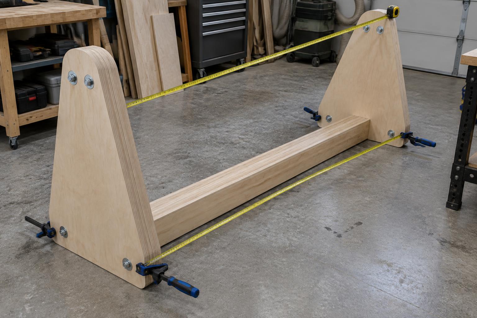
Concept reference — not a fabrication drawing - Assemble on a flat floor; measure both diagonals of the cradle footprint and equalize them before the glue sets.
- Confirm the frame-to-frame spacing matches the top's 112 in. length and the pivot centerline.
- Through-bolt the joint into solid lamination, never a single ply.
Verify the assembled footprint approaches the full 62 in. width of the top before the glue cures.
- 09
Mount casters and floor stabilizers
Six casters carry the cradle when it rolls; four stabilizers take the load whenever it works or tilts.
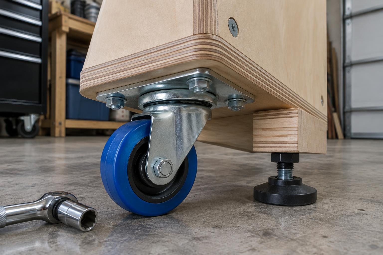
Concept reference — not a fabrication drawing - Glue and fasten the caster pads to the end frames as full lamination schedules; through-bolt the six casters to those pads.
- Fit the four leveling feet into their laminated blocks, two per end frame near the outer corners.
- Measure the actual caster mounting height — the final pivot height is set from this number, not the drawing.
- 10
Fit pivot and bearings
The last cradle step — and the one that waits on measured mass, center of gravity, and reactions.
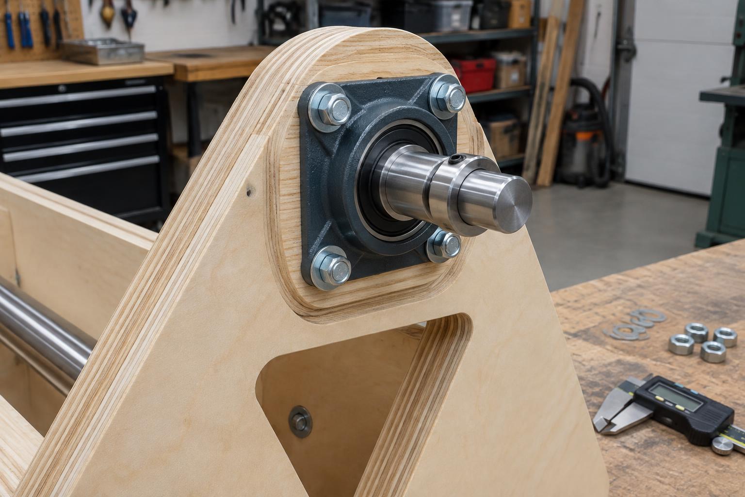
Concept reference — not a fabrication drawing - Weigh the finished top and locate its center of gravity along the 62 in. width.
- Size the shaft and bearings from the measured reactions; only then bore and bolt the flange bearings to their pads.
- Set the axis at 34–36 in. above the floor — never below the 31.1 in. corner-swing minimum.
- Install the positive locking pins at the horizontal and vertical positions and verify engagement.
Not released: pivot shaft, bearings, locks, and drive remain engineering holds until the moving mass is measured.
- 11
Final checks
Prove the cradle before the top ever swings on it.
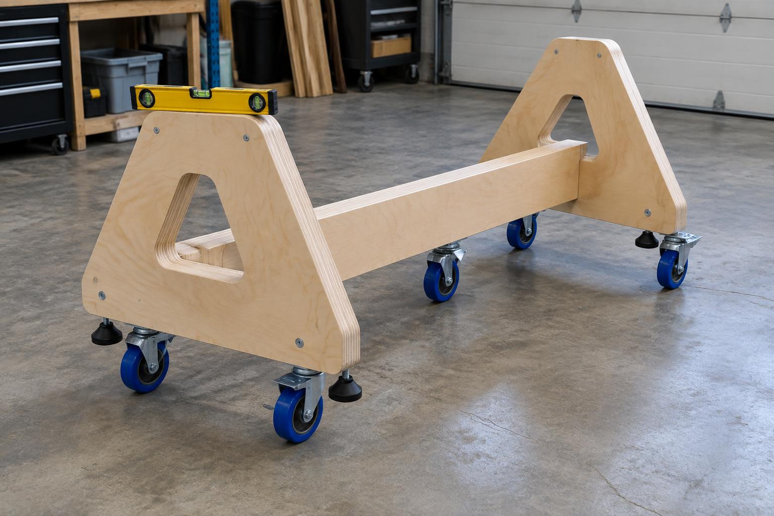
Concept reference — not a fabrication drawing - Roll the loaded cradle in every direction on casters; check swivel action and floor clearance.
- Deploy the stabilizers, lift the casters clear, and confirm the cradle is dead solid with no rock.
- Re-check frame plumb, footprint squareness, and every fastener after the first loaded roll.
- Re-verify the restoring-moment math against the as-built footprint and the measured top weight.