Shop project 03 · Brief revision 1.1
LowRider v4 CNC tilt table
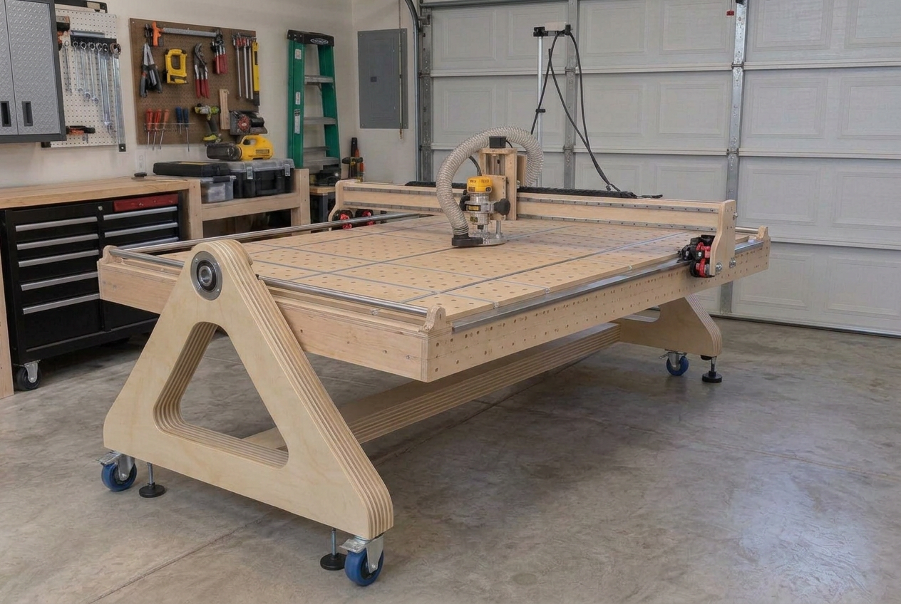
A freestanding, movable CNC and assembly table sized around untrimmed 48.5 × 96.5 in. plywood. Its plywood torsion-box top rotates about 90 degrees for storage without any attachment to the garage walls or ceiling.
- Machine
- LowRider CNC v4
- Required stock
- 48.5 × 96.5 in. minimum
- Structural top
- 62 × 112 in. candidate
- MDF module field
- 53 × 97 in. proposed
- Track-framed deck
- 54.5 × 98.5 in. proposed
- Required work field
- 49 × 97 in. within deck
- Work zero
- Front-left square edge rail
- Working height
- About 36 in. target
- Storage
- About 90° vertical
Readiness gate
The rotation system is not released for fabrication.
The pivot shaft, bearings, controlled drive, locks, clearances, moving mass, center of gravity, and full sweep still require measurement and engineering. Numeric planning values are not approval to build or operate the mechanism.
Project sequence
Build the machine that builds the table
The temporary deck stays available until every dependent jig, cabinet, and permanent-table part has been machined and checked.
- 01Finish the lumber cart and cherry-slab work to clear space and manage stock.Lumber cart
- 02Build the temporary deck and commission the LowRider v4.Stage 01 · Temporary deck
- 03Cut early Baltic-birch assembly jigs.Cradle build guide
- 04Mill the mobile cradle's plywood members on the temporary table.Stage 04 · Mobile cradle
- 05Build the compact MacBook and gantry-storage cabinet.Stage 08 · Storage
- 06Complete the permanent torsion-box table only after dependent machining and measurements.Stage 02 · Torsion box
Dimension control
Requirements are not the same as released dimensions
| Item | Planning value | Status |
|---|---|---|
| Required stock capacity | At least 48.5 × 96.5 in., untrimmed | Confirmed requirement |
| Structural top | 62 × 112 in. | Provisional |
| Torsion-box core | Module-matched rib grid (ribs under every T-track, lane centers, and between hole columns); 4.25 in. structural thickness | Provisional |
| MDF working surface | Ten removable 3/4 in. modules | Proposed change |
| Work-zero reference | Removable hard-maple L-rail at front-left: 49 × 1-1/2 × 3/4 in. front/Y0 leg and 97 × 1-1/2 × 3/4 in. left/X0 leg, joined by a 1-1/2 × 1-1/2 in. half-lap cut 3/8 in. deep in each piece. Final height above the MDF, offsets, and mounting-hole locations remain subject to the verified machine envelope. | Hold |
| MDF module field | 53 × 97 in.; five equal 10 in. lanes with four 3/4 in. longitudinal and one 3/4 in. transverse T-track seam | Proposed change |
| Track-framed deck | 54.5 × 98.5 in.; adds a continuous 3/4 in. T-track perimeter around the 53 × 97 in. module field | Proposed change |
| Required work field | 49 × 97 in. minimum reference field within the larger modular deck | Hold |
| Base / cradle | End frames are rounded-triangle plywood laminations milled on the temporary CNC table; footprint approaches the 62 in. top width; pivot axis 34–36 in. above floor (31.1 in. min) | Provisional |
| Pivot axis | 33 in. nominal | Hold |
| Casters | Six matching 6 × 2 in. polyurethane | Provisional |
Stability check · 62 in. width, 34–36 in. pivot
Overturning moment and lateral stiffness
A first-principles hand check using the 62 in. base footprint, a 35 in. pivot axis, and estimated weights. It tells us whether the geometry is in the right neighbourhood; it is not a substitute for weighing the finished top and locating its real center of gravity.
Weight take-off
| Plywood torsion-box top62 × 112 in.; two 3/4 in. skins over a 3/4 in. rib grid | ≈ 315 lb |
| Ten removable MDF modules3/4 in. MDF, full field | ≈ 150 lb |
| T-track, datum rail, dogs, edging, fastenersFour longitudinal tracks, one transverse track, continuous perimeter track, and front-left L-shaped reference rail | ≈ 40 lb |
| Rotating assembly subtotalEverything that swings about the pivot axis | ≈ 500 lb |
| Cradle, casters, stabilizersLaminated plywood end frames, LSL center spine, hardware | ≈ 260 lb |
| Standing weight on the floorRotating assembly plus cradle | ≈ 760 lb |
Overturning results
Combined center of gravity (vertical storage)
Provisional27.8 in. above floor
(500 lb × 35 in. + 260 lb × 14 in.) ÷ 760 lb
Restoring moment about a caster line
Provisional23,560 in-lb (1,963 ft-lb)
760 lb × 31 in. half-footprint (62 in. base width)
Side force that would overturn it
Provisional357 lb at the top edge
23,560 in-lb ÷ 66 in. lever (35 in. pivot + 31 in. half-width)
Factor of safety, 50 lb accidental shove
Provisional7.1
23,560 in-lb ÷ (50 lb × 66 in.)
Floor slope that would overturn it
Provisional48.1 degrees
arctan(31 in. ÷ 27.8 in.) — far beyond any garage slab
Unbalance per inch of CG offset from the axis
Hold500 in-lb (42 ft-lb) per inch
500 lb × 1 in.; about 16 lb of hand force at the 31 in. edge
Lateral stiffness
| Direction | Model | Stiffness | Sway |
|---|---|---|---|
| Weak axis — push along the 112 in. tilt axis | Each end frame as a 35 in. cantilever, 2.25 in. lamination (three 3/4 in. plies), 14 in. effective neck width, E ≈ 1.3 × 10⁶ psi, I = 13.3 in⁴ | ≈ 1,210 lb/in per frame; ≈ 1,450 lb/in for the pair after a 40 percent derate for spine torsion and bolted joints | 0.034 in. under a 50 lb shove |
| Strong axis — push across the 62 in. width | Triangle acts as a deep shear panel roughly 40 in. front-to-back | Well above 20,000 lb/in | Under 0.003 in. — effectively rigid |
| Rolling on casters | Six 6 × 2 in. polyurethane swivel casters, stem and tread compliance plus swivel lash | Governs; an order of magnitude softer than the plywood frames | Tenths of an inch of sway — never rotate the top while resting on casters |
Conditions the numbers depend on
- Set all four floor stabilizers down and lift the casters clear before any rotation or vertical parking.
- Spread the stabilizers to the full 62 in. footprint; narrowing them reduces the restoring moment proportionally.
- Engage both positive locking pins in the vertical position; the numbers above assume no reliance on friction.
- Remove the gantry, router, stock, hoses, and clamps before tilting; loose mass shifts the center of gravity unpredictably.
- Keep MDF modules installed symmetrically during a tilt so the rotating CG stays near the axis.
- Weigh the finished top and locate its true CG before trusting the unbalance figure; that value is on hold.
Working field
Ten removable MDF modules
Five equal 10 in. lanes repeat across two rows. Four 3/4 in. longitudinal tracks and one 3/4 in. transverse midpoint track create a 53 × 97 in. module field. A continuous 3/4 in. perimeter track makes the complete track-framed deck 54.5 × 98.5 in.—larger than the required 49 × 97 in. work field. The square maple L-rail sits immediately outside the track and establishes repeatable Y0 and X0 references.
Ten identical installed modules · continuous 3/4 in. perimeter T-track · spare panels tracked separately
Construction sequence
Eight stages, in dependency order
0/45 tasks savedMachine-readable layout for jig design (JSON)
{"units":"inches","origin":"front-left outside corner of the track-framed deck; X along 98.5 in. length, Y across 54.5 in. width","deck":{"length":98.5,"width":54.5},"trackWidth":0.75,"longitudinalTrackBandsY":[[0,0.75],[10.75,11.5],[21.5,22.25],[32.25,33],[43,43.75],[53.75,54.5]],"transverseTrackBandsX":[[0,0.75],[48.875,49.625],[97.75,98.5]],"modules":"10 identical 10 x 48.125 in.; lanes Y 0.75-10.75, 11.5-21.5, 22.25-32.25, 33-43, 43.75-53.75; rows X 0.75-48.875, 49.625-97.75","modulePattern":{"note":"identical in every module, measured from module front-left corner","holesX":[3.0625,10.0625,17.0625,24.0625,31.0625,38.0625,45.0625],"holesY":[2.5,7.5],"count":14,"diameter_mm":20},"holes":[[3.8125,3.25],[3.8125,8.25],[10.8125,3.25],[10.8125,8.25],[17.8125,3.25],[17.8125,8.25],[24.8125,3.25],[24.8125,8.25],[31.8125,3.25],[31.8125,8.25],[38.8125,3.25],[38.8125,8.25],[45.8125,3.25],[45.8125,8.25],[3.8125,14],[3.8125,19],[10.8125,14],[10.8125,19],[17.8125,14],[17.8125,19],[24.8125,14],[24.8125,19],[31.8125,14],[31.8125,19],[38.8125,14],[38.8125,19],[45.8125,14],[45.8125,19],[3.8125,24.75],[3.8125,29.75],[10.8125,24.75],[10.8125,29.75],[17.8125,24.75],[17.8125,29.75],[24.8125,24.75],[24.8125,29.75],[31.8125,24.75],[31.8125,29.75],[38.8125,24.75],[38.8125,29.75],[45.8125,24.75],[45.8125,29.75],[3.8125,35.5],[3.8125,40.5],[10.8125,35.5],[10.8125,40.5],[17.8125,35.5],[17.8125,40.5],[24.8125,35.5],[24.8125,40.5],[31.8125,35.5],[31.8125,40.5],[38.8125,35.5],[38.8125,40.5],[45.8125,35.5],[45.8125,40.5],[3.8125,46.25],[3.8125,51.25],[10.8125,46.25],[10.8125,51.25],[17.8125,46.25],[17.8125,51.25],[24.8125,46.25],[24.8125,51.25],[31.8125,46.25],[31.8125,51.25],[38.8125,46.25],[38.8125,51.25],[45.8125,46.25],[45.8125,51.25],[52.6875,3.25],[52.6875,8.25],[59.6875,3.25],[59.6875,8.25],[66.6875,3.25],[66.6875,8.25],[73.6875,3.25],[73.6875,8.25],[80.6875,3.25],[80.6875,8.25],[87.6875,3.25],[87.6875,8.25],[94.6875,3.25],[94.6875,8.25],[52.6875,14],[52.6875,19],[59.6875,14],[59.6875,19],[66.6875,14],[66.6875,19],[73.6875,14],[73.6875,19],[80.6875,14],[80.6875,19],[87.6875,14],[87.6875,19],[94.6875,14],[94.6875,19],[52.6875,24.75],[52.6875,29.75],[59.6875,24.75],[59.6875,29.75],[66.6875,24.75],[66.6875,29.75],[73.6875,24.75],[73.6875,29.75],[80.6875,24.75],[80.6875,29.75],[87.6875,24.75],[87.6875,29.75],[94.6875,24.75],[94.6875,29.75],[52.6875,35.5],[52.6875,40.5],[59.6875,35.5],[59.6875,40.5],[66.6875,35.5],[66.6875,40.5],[73.6875,35.5],[73.6875,40.5],[80.6875,35.5],[80.6875,40.5],[87.6875,35.5],[87.6875,40.5],[94.6875,35.5],[94.6875,40.5],[52.6875,46.25],[52.6875,51.25],[59.6875,46.25],[59.6875,51.25],[66.6875,46.25],[66.6875,51.25],[73.6875,46.25],[73.6875,51.25],[80.6875,46.25],[80.6875,51.25],[87.6875,46.25],[87.6875,51.25],[94.6875,46.25],[94.6875,51.25]],"ribCenterlinesDeck":{"longitudinalY":[0.375,5.75,11.125,16.5,21.875,27.25,32.625,38,43.375,48.75,54.125],"crossX":[0.375,7.3125,14.3125,21.3125,28.3125,35.3125,42.3125,49.25,56.1875,63.1875,70.1875,77.1875,84.1875,91.1875,98.125],"thickness":0.75},"datumRails":"maple X0 rail outside left edge (X<0), Y0 rail outside front edge (Y<0)","assumption":"deck centered on the 112 x 62 in. torsion box (6.75 in. end / 3.75 in. side margins); hole coordinates on hold until machine-envelope test"}Machine-readable module spec (JSON)
{"units":"inches","origin":"front-left corner of the module; X along the 48.125 in. length, Y across the 10 in. width","module":{"length":48.125,"width":10,"thickness":0.75,"material":"3/4 in. MDF"},"holes":{"count":14,"diameter_mm":20,"diameter_in":0.787,"xFromLeftEnd":[3.0625,10.0625,17.0625,24.0625,31.0625,38.0625,45.0625],"yFromFrontEdge":[2.5,7.5],"coordinates":[[3.0625,2.5],[3.0625,7.5],[10.0625,2.5],[10.0625,7.5],[17.0625,2.5],[17.0625,7.5],[24.0625,2.5],[24.0625,7.5],[31.0625,2.5],[31.0625,7.5],[38.0625,2.5],[38.0625,7.5],[45.0625,2.5],[45.0625,7.5]]},"edges":"all four edges butt against 3/4 in. T-track seams; no edge banding","ribNote":"longitudinal ribs at Y 0.375/5/9.625 and cross ribs at X 0.375/6.5625+7k/47.75 (module-local) keep every hole in an open bay","assumption":"hole coordinates on hold until machine-envelope test"}- 010/5
Build the temporary CNC deck
Commission the LR4 and machine later project parts before committing to the permanent table.
Prerequisite
Count the LSL, plywood, MDF, ties, fasteners, and both CNC shipments.
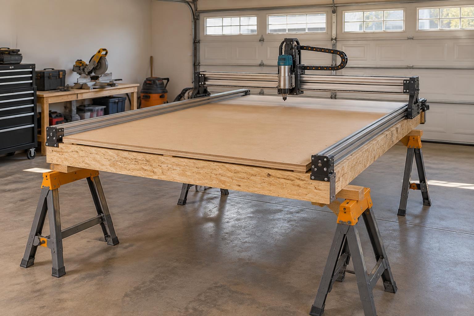
Concept reference · temporary commissioning deck on four BORA sawhorses - Set four BORA Workhorse XT sawhorses on a level floor.
- Build the provisional 62 × 112 in. LSL frame with supported sheet seams.
- Install the plywood deck and replaceable 1/4 in. MDF wear layer.
- Map every screw, restraint, hold-down, rail fixing, and metal keep-out.
- Commission the LR4, verify square and reach, and prove test cuts.
Hold point
Do not cut final gantry tubes or fix rail and belt mounts until oversized-sheet travel is verified.
Acceptance
The machine makes proven test cuts and can produce jigs and permanent-table components.
- 020/5
Dry-fit the torsion box
Build a light, stiff plywood box from interlocking ribs, reinforced splices, rims, and continuous skins.
- Plan size
- 62 × 112 in. (provisional structural top)
- Structural thickness
- 4.25 in. — two 3/4 in. plywood skins over the rib grid
- Rib grid
- Redesigned to suit identical modules: 13 longitudinal ribs (under all six long tracks, down each lane center, plus two edge rims) and 17 cross ribs (under the three transverse tracks, one between each hole column, plus two end rims); ribs interlock half-depth
- Dog-hole grid rule
- Every module has the identical 14-hole pattern (two rows at 2.5 and 7.5 in. across, seven columns at 3.0625 + 7k in. along); ribs are placed around that pattern so no hole ever lands on a rib
- Above the box
- The 3/4 in. MDF modules of Stage 03 add on top of the upper skin
Prerequisite
The temporary CNC is commissioned and actual plywood thickness is recorded.
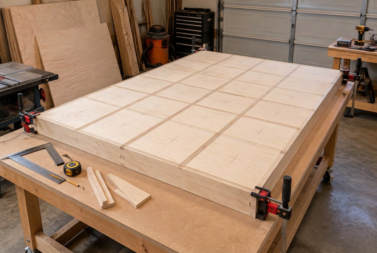
Concept reference · interlocking rib grid before the continuous skins close the box - Cut 13 longitudinal ribs (spliced and reinforced where over 8 ft) and 17 cross ribs on the module-matched layout.
- Fit half-depth slots to measured material with tested clearance.
- Reinforce the Y = 56 splice and all skin seams.
- Dry-fit on a verified flat platform and compare diagonals.
- Photograph backing, clearances, and service access before closing the box.
Hold point
Do not bond skins until inserts, dog holes, track lines, pivots, locks, and backing locations are coordinated.
Acceptance
The grid seats fully without twist, all seams are supported, and the reference plane remains flat.
- 030/6
Fit the modular work surface
Ten equal-width removable MDF modules create a deck larger than the required CNC work field, divided by five internal T-track lines, surrounded by perimeter T-track, and registered to a square front-left X0/Y0 reference rail.
- MDF module field
- 53 × 97 in., including four 3/4 in. longitudinal T-track seams and one 3/4 in. transverse seam
- Track-framed deck
- 54.5 × 98.5 in., including a continuous 3/4 in. T-track perimeter on all four sides
- Required work field
- 49 × 97 in. minimum, contained within the larger modular deck
- Module size
- Each module is 10 × 48.125 in.; two identical modules per lane and five equal-width lanes
- Module thickness
- 3/4 in. MDF, bearing on the box's continuous upper skin
- Dog-hole grid
- Identical pattern in all ten modules: 20 mm holes, two rows 2.5 and 7.5 in. from the module edge, seven columns 7 in. apart starting 3.0625 in. from the module end; modules are fully interchangeable; deck centered on the box; positions on hold until machine-envelope testing
- Surface build-up
- 4.25 in. box + 3/4 in. module ≈ 5 in. total working height over the rib core
Prerequisite
Actual track, cross junctions, ledges, MDF thickness, and reinforced insert coupons are approved.
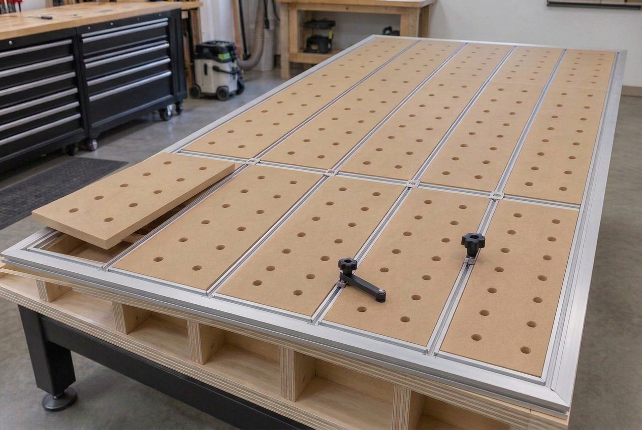
Concept reference · ten equal MDF modules, internal tracks, perimeter track, and maple datum rails - Fit two identical 10 × 48.125 in. modules in each of five equal-width lanes.
- Test underside rabbets so every module bears on the continuous plywood skin.
- Install four longitudinal tracks, the transverse midpoint track, and a continuous 3/4 in. T-track perimeter around all four sides of the MDF field.
- Fit a removable hard-maple L-rail immediately outside the perimeter track: 49 × 1-1/2 × 3/4 in. along the front for Y0 and 97 × 1-1/2 × 3/4 in. along the left for X0. Half-lap the corner 1-1/2 × 1-1/2 in. and 3/8 in. deep in each rail.
- Add only reviewed 20 mm dog holes that follow the identical per-module pattern (rows 2.5 / 7.5 in., columns 3.0625 + 7k in.) and clear structure and metal.
- Match the retention pattern on ten spare modules after the installed set is proven.
Hold point
The 53 × 97 in. module field, 54.5 × 98.5 in. track-framed deck, 49 × 97 in. minimum work field, hard-maple rail blanks, and the identical per-module dog-hole pattern are specified; final proud height, offsets, mounting holes, module running clearance, covers, actual dog-hole coordinates, and insert schedule remain unreleased until the machine envelope is tested.
Acceptance
Modules sit flat and remove cleanly, track access remains clear, and the front-left rail is straight, square, repeatable, and outside every cutter, gantry, clamp, and module keep-out.
- 040/8
Build the mobile cradle
A freestanding plywood base carries the pivots while keeping the center open for the full rotation sweep. Each end frame is a fluid rounded-triangle form: rounded triangular plywood layers milled on the temporary CNC table, then laminated together into a deep sculptural end frame. Pivot axis sits 34–36 in. above the floor; the base footprint approaches the 62 in. top width so the assembly is stable with the top vertical.
Prerequisite
The temporary table can machine cradle members; caster height, plate patterns, table mass, center of gravity, and pivot reactions are measured.
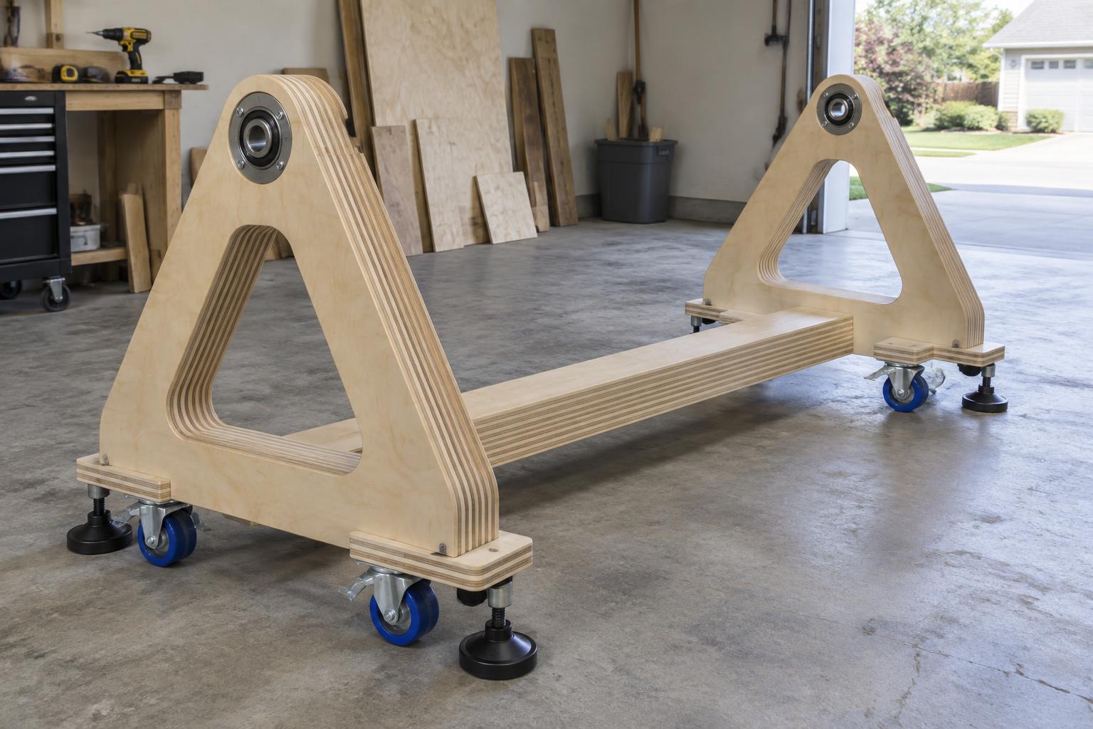
Concept reference · mobile plywood cradle, laminated where required, milled on the temporary table - Mill the rounded triangular plywood layers for both end frames on the temporary CNC table — the CNC-cut curves give the fluid, sculpted shape no straight-saw layout can match.
- Laminate the rounded triangular layers into each end frame with full glue coverage and clamping; stack enough layers for the required depth and pivot bearing support.
- Cut the single central spine from a 2 × 6 LSL — factory-laminated, so no glue-up; mill its ends square and to length on the temporary CNC table.
- Glue-and-fasten the bearing pads, caster pads, and lock backing as full lamination schedules.
- Through-bolt six matching 6 × 2 in. polyurethane casters to solid laminated pads.
- Fit four stabilizers and four working legs for repeatable support.
- Set the pivot axis 34–36 in. above the floor (31.1 in. absolute minimum for the 62 in. top's corner swing).
- Leave the cradle center open and measure every hardware protrusion.
Hold point
Do not release base dimensions until the entire moving envelope and garage travel route are checked.
Acceptance
The unloaded base rolls without racking and rests solidly on supports with caster loads relieved.
- 050/5
Prototype pivots and locks
Separate hardware carries rotation, controls movement, and positively locks both end positions.
Prerequisite
Completed moving mass, center of gravity, worst-case leverage, and bearing reactions are known.
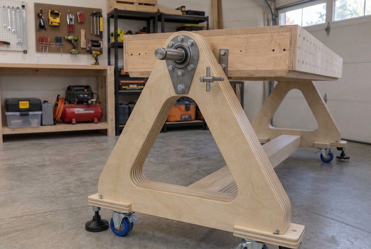
Concept reference only · bearing, shaft, retention, and positive lock require engineering - Align bearing and shaft assemblies at both short ends.
- Transfer reactions through steel plates and through-bolted plywood backing.
- Provide axial shaft retention independent of the drive.
- Fit visible steel-to-steel lock pins at horizontal and vertical positions.
- Select a rated controlled drive only after measured-load calculations.
Hold point
The nominal 1 in. shaft is only a space allowance; no bearing, shaft, actuator, winch, or lock is released.
Acceptance
A reviewed prototype proves alignment, full pin engagement, retention, and a continuous structural load path.
- 060/6
Install and verify the LR4
Set the LowRider v4 around the real work envelope rather than assuming the support field equals cutter travel.
Prerequisite
The table is locked horizontal, supported on working legs, level, and the surface system is proven.
Concept reference · horizontal CNC mode with oversized sheet supported flat - Install the LR4 round guide rail and opposite flat wheel runway to measured geometry.
- Indicate the front-left reference rail square to machine travel, record its X0/Y0 offsets, and verify repeatability after removal and reinstallation.
- Verify travel with a 48.5 × 96.5 in. stock record at full size.
- Check cutter sweep, dust shoe, clamps, lead-ins, hard stops, belts, and carriage clearance separately.
- Surface only to the measured safe depth above metal and required rabbet lips.
- Prove CAM output and the Jackpot controller workflow with the MacBook.
Hold point
Do not mark oversized stock machine-ready until actual outside-profile travel and fixture clearance pass.
Acceptance
Stock footprint, support, tool-center travel, fixture keep-outs, and the calibrated front-left X0/Y0 datum are documented as separate envelopes.
- 070/5
Commission the controlled tilt
Exercise the full sweep only with the machine and every loose item removed from the moving top.
Prerequisite
Pivot, drive, locks, supports, clearances, mass, and center of gravity have passed review.
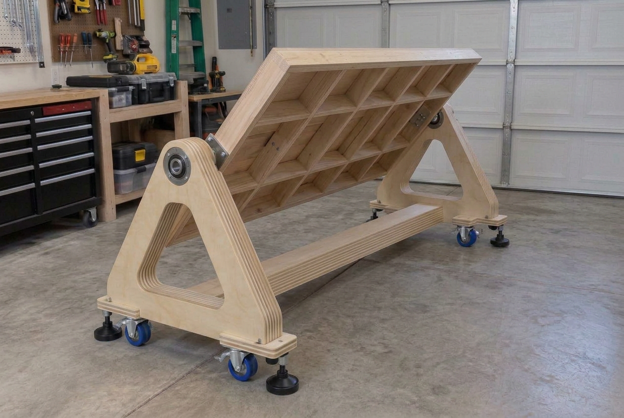
Concept reference · controlled sweep with gantry, router, stock, and loose items removed - Remove gantry, router, stock, hoses, covers, jigs, clamps, and loose fittings.
- Deploy stabilizers and verify the cradle is level and immobile.
- Release supports and locks only in the reviewed order.
- Rotate under positive control while observing both ends and the floor sweep.
- Engage both storage locks and verify visible full pin engagement.
Hold point
Never rely on a drive or gas spring as a structural lock, and never stand inside the sweep.
Acceptance
The top travels without collision, uncontrolled acceleration, binding, racking, or partial lock engagement.
- 080/5
Verify storage and changeover
Store the top near vertical to reclaim floor space while the removed gantry lives in its own compact cabinet.
Prerequisite
Both vertical locks are engaged and retained; all loose equipment is accounted for.
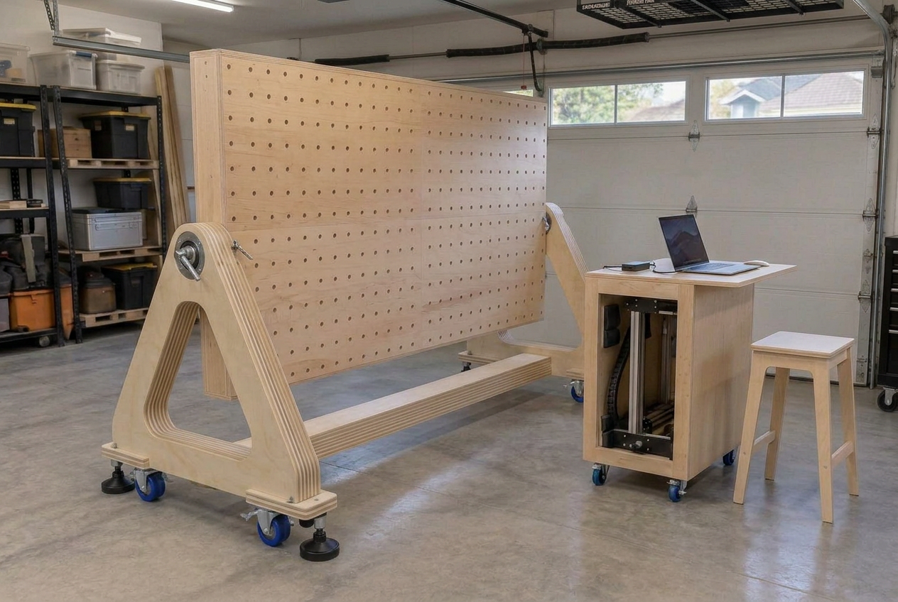
Concept reference · vertical storage mode and separate gantry cabinet - Measure the real stored height, footprint, hardware projection, and garage clearances.
- Confirm the 112 in. length stays horizontal and the 62 in. width clears vertically.
- Store the removed gantry safely in the separate front-access cabinet.
- Check the seated MacBook position from the 23 in. stool.
- Record the complete reverse sequence for returning to CNC mode.
Hold point
About 66 in. stored height is an allowance, not a guaranteed clearance.
Acceptance
The table fits the garage and travel route without wall or ceiling attachment and changes modes repeatably.
Before fabrication
Open decisions
These questions keep provisional geometry from becoming an accidental cut list. Open each group before releasing dependent parts.
Machine envelope
- What are the verified cutter-center travel bounds for outside-profiling 48.5 × 96.5 in. stock?
- Do the dust shoe, clamps, fixtures, lead-ins, hard stops, belts, and carriage clear the full operation?
- Does the retained 62 × 112 in. top remain adequate after actual LR4 geometry is measured?
Surface and workholding
- Which track family, genuine cross junction, ledge, and perimeter extrusion are selected?
- What final proud height, offset, fastening pattern, and calibration procedure will make the specified hard-maple front-left datum rail repeatable and clear of the full machine envelope?
- What do the module-fit, rabbet, insert, screw-recess, and 20 mm dog-hole coupons prove?
- Will the four covers remain partial, or will cover sizes and material quantities be revised?
Rotation and base
- What are the measured moving mass, center of gravity, and worst-case leverage through the sweep?
- Which bearings, shafts, plates, retainers, locks, and controlled drive are released?
- Which plywood cradle members require lamination, and what lamination schedule and adhesive are approved? (The center spine is settled: a single 2 × 6 LSL.)
- What exact caster height, bolt patterns, stabilizer details, and working-leg lengths are required?
- Does the complete sweep clear the cradle, floor, cables, hardware, garage, and travel route?