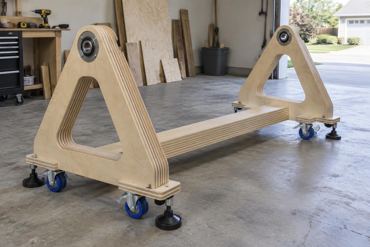
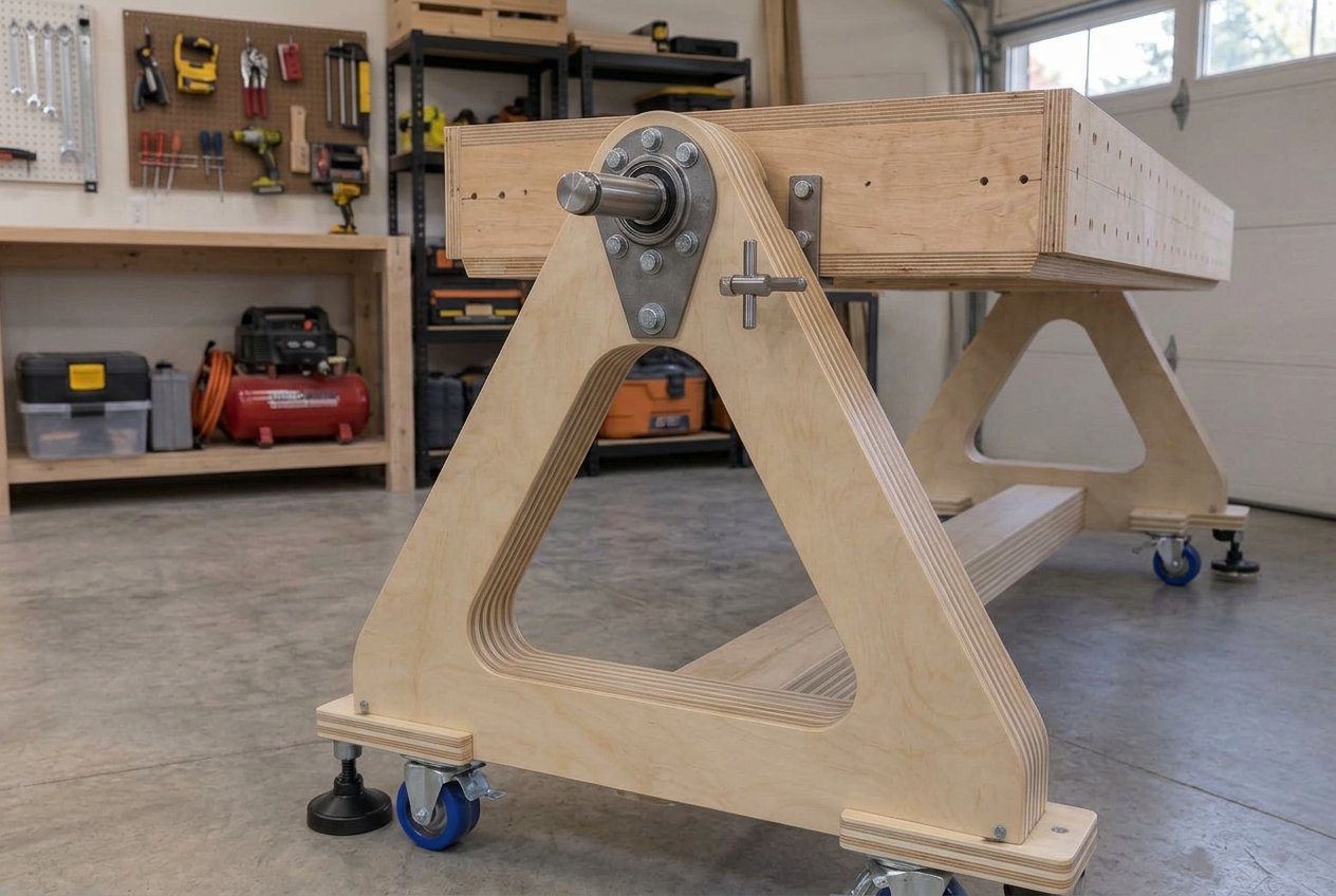
A freestanding laminated-plywood base that carries the 62 × 112 in. torsion-box top, rotates it between working and storage positions, and rolls anywhere in the garage — without touching a wall.
Concept reference · not a released fabrication drawing
Overall footprint
≈ 62 × 120 in.
Pivot axis height
34–36 in. above floor
Corner-swing minimum
31.1 in. (62 in. top)
Carried top
62 × 112 × ~5 in. torsion box
Mobility
6 casters + 4 stabilizers
Structure
Laminated plywood, CNC-milled
Readiness gate
Pivot and bearing values are on hold.
Shaft diameter, bearing selection, and locking hardware require measured moving mass, center of gravity, and worst-case reactions. The dimensions below are planning values, not approval to fabricate the rotation hardware.
Bill of components
Six parts carry the whole table
01
End frame
ProvisionalQty 2
Material
3/4 in. Baltic birch plywood, rounded triangular layers milled on the temporary CNC table, laminated with full glue coverage
Dimensions
Rounded triangle, ≈ 34–36 in. to the pivot vertex, ≈ 62 in. wide at the floor; enough laminated layers for the required depth and bearing support
CNC-cut curves give the fluid shape; straight-saw layouts cannot match the radius transitions.
Striped plies remain visible on every rounded edge — the lamination is the finish.
Wide triangular stance resists overturning with the 62 in. top locked vertical.
Open center of the triangle keeps weight down without losing stiffness.
02
Central spine
ProvisionalQty 1
Material
Single 2 × 6 LSL (laminated strand lumber, 1-3/4 × 5-1/2 in.) — factory-laminated, so no shop lamination schedule is needed
Dimensions
Single central beam, ≈ 112–120 in. long (exactly 10 ft at the 120 in. length — a single 12 ft LSL covers it with trim margin), joining the two end frames at floor level; the 5-1/2 in. depth carries the bending load in one piece
One spine only — no side rails and no middle crossbeam (a capital-I floor plan).
LSL is straight, dimensionally stable, and stronger than solid lumber — it replaces the laminated plywood spine outright.
Cut to length and squared on the temporary CNC table or with a guided circular saw; no glue-up required.
Leaves the cradle center open for the full rotation sweep of the 62 in. top.
Carries the end frames' spacing and resists racking along the 112 in. top length.
03
Pivot shaft
Hold — not releasedQty 2 (one per end)
Material
Steel shaft with steel reinforcement plates, through-bolted plywood bearing pads, axial retention independent of the drive
Dimensions
Axis at 34–36 in. above the floor; 31.1 in. is the absolute minimum for the 62 in. top's corner swing; diameter set by engineering
Mounted near the top vertex of each rounded-triangle end frame.
Positive locking pins engage at horizontal (working) and vertical (storage) positions.
Rotation hardware is separate from any future controlled drive.
04
Bearings
Hold — not releasedQty 2 (one per pivot)
Material
Steel flange bearing blocks mounted on laminated bearing pads with steel reinforcement plates and through-bolts
Dimensions
Sized to the pivot shaft after mass, center of gravity, and worst-case reactions are measured
Reactions transfer through steel plates into the laminated end-frame material, never into a single plywood layer.
Bearing pads glue-and-fasten to the end frame as a full lamination schedule.
Bearing selection waits on measured moving mass — not released for fabrication.
05
Casters
ProvisionalQty 6
Material
Matching 6 × 2 in. polyurethane-wheel swivel casters, through-bolted to solid laminated plywood pads
Dimensions
6 in. diameter × 2 in. wide wheels; three per end frame
Polyurethane tread rolls quietly and protects the garage's concrete floor.
Through-bolts pass into solid laminated pads — never into a single skin.
Caster height is measured before final pivot height is fixed.
06
Floor stabilizers
ProvisionalQty 4
Material
Black adjustable leveling feet threaded into solid laminated blocks on the base
Dimensions
Adjusted down to relieve the casters and seat the cradle solidly before any rotation
Deployed whenever the table is worked on or tilted — the casters never carry a rotating load.
Two per end frame, one near each outer corner.
Complemented by four working legs for repeatable support height.
Pivot hardware
Where the triangle meets the shaft
The bearing block, steel shaft, reinforcement plate, through-bolts, and positive locking pin all sit at the top vertex of each rounded-triangle end frame.
Concept reference only · pivot hardware requires engineering before fabrication
Standing rules
What this cradle must always respect
Nothing attaches to the garage walls or ceiling — the cradle is fully freestanding.
Every cradle member is milled flat, square, and to dimension on the temporary CNC table.
Pivot, bearings, locks, and drive remain a hold until moving mass and center of gravity are measured.
Concept images are references, not released fabrication drawings.